My S13 SR20DET Prep

 07-15-2008, 03:36 PM
#183
Contributing Member
Thread Starter
Join Date: Sep 2002
Location: Starkville, MS.
Posts: 1,192
Rocker Arm Stopper Install
Got a set of rocker arm stoppers in.
Tools needed:
Socket wrench
Socket extension
10mm socket
11mm socket
Dremel tool
Small flathead screwdriver
Torque wrench
Afraid of redlining or mishifting and floating a valve...get a set of rocker arm stoppers, or so they said.
Greddy rocker arm stoppers.
Start by removing your coilpack cover and valve cover. Check the FSM for the procedure on removing this as it needs to be done in a specific order.
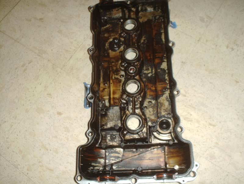
Backside of the cover.
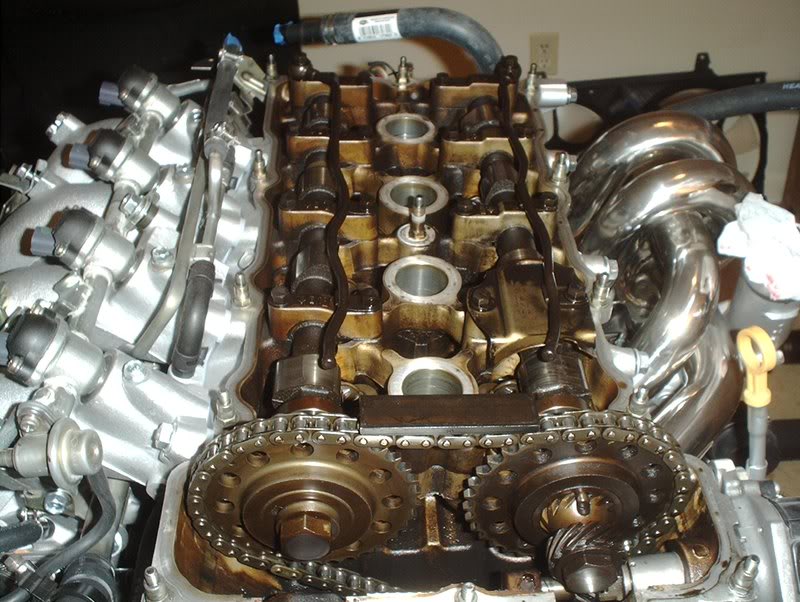
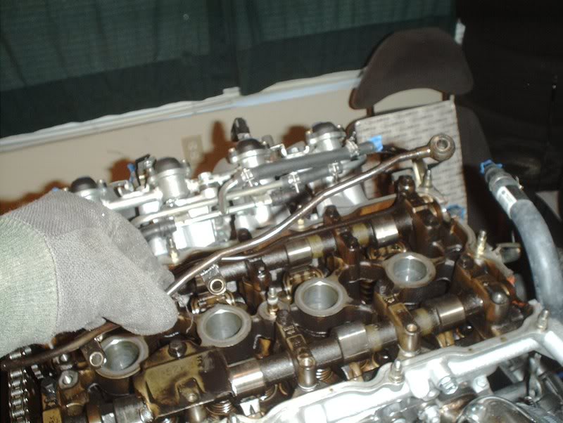
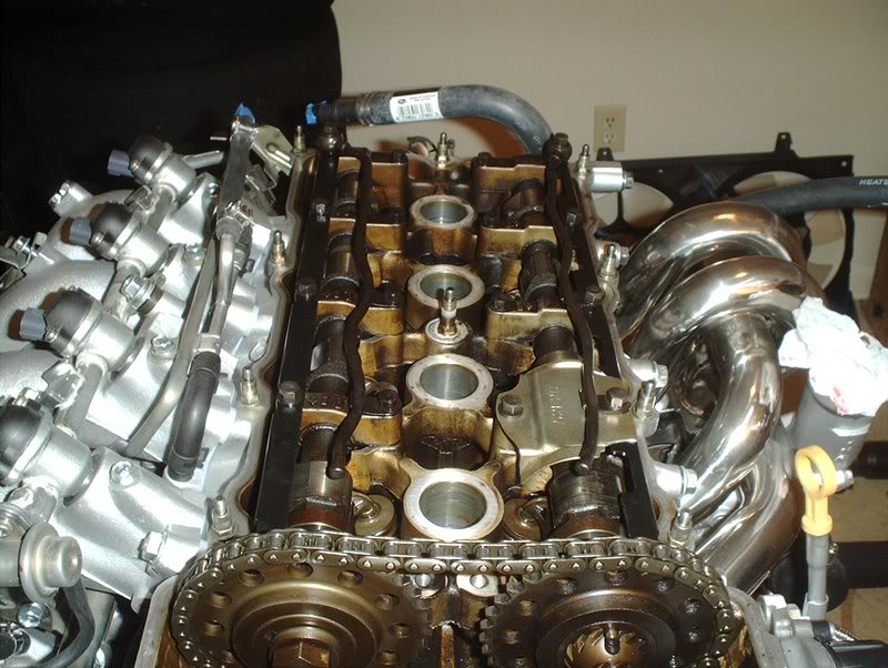
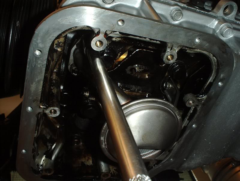
Internals, pretty filthy under there.
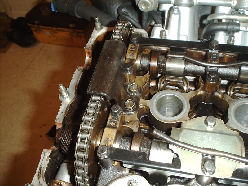
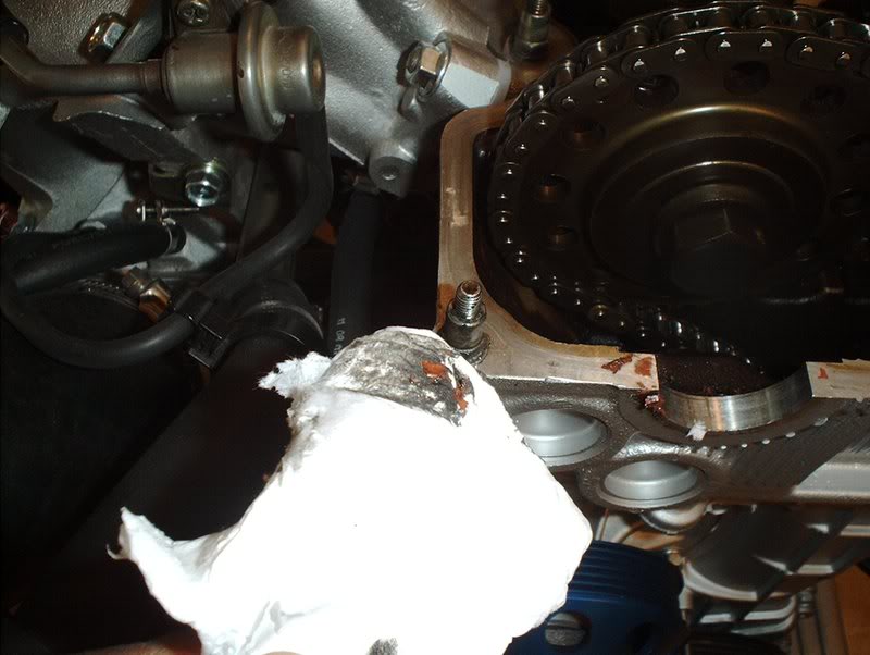
I started by removing the chain guide as you won't be able to get to the two camshaft bracket bolts near the chain guide with a socket because the guide will block you. You need a 11mm socket for this.
Off
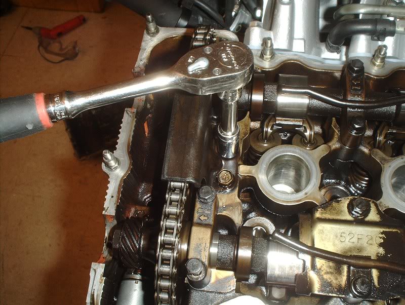
Next, I removed the camshaft bolts. Use a 10mm socket for these.
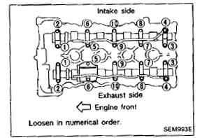
This needs to be done in a specific order as well so follow the FSM instructions.
I cheated a little as I didn't completely remove all the inner bolts. I merely loosened them.
Be very careful when you remove the camshaft bracket bolts as there are very small washers on each of them and the bolts on the end of the oil tubes have two washers, one on the top of the oil tube and one on the bottom. MAKE SURE that you don't let any of these washers slide off and fall into your engine. This is where I used a small flathead screwdriver to snake into the washers on the oil tubes and ****** them off so they wouldn't fall in.
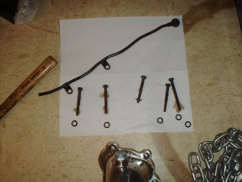
When you remove the bolts place them in the order that they are in the engine so you can put the same bolt back in the same place.
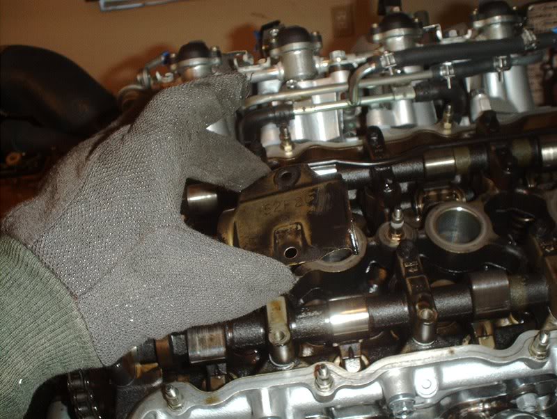
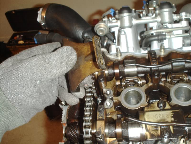
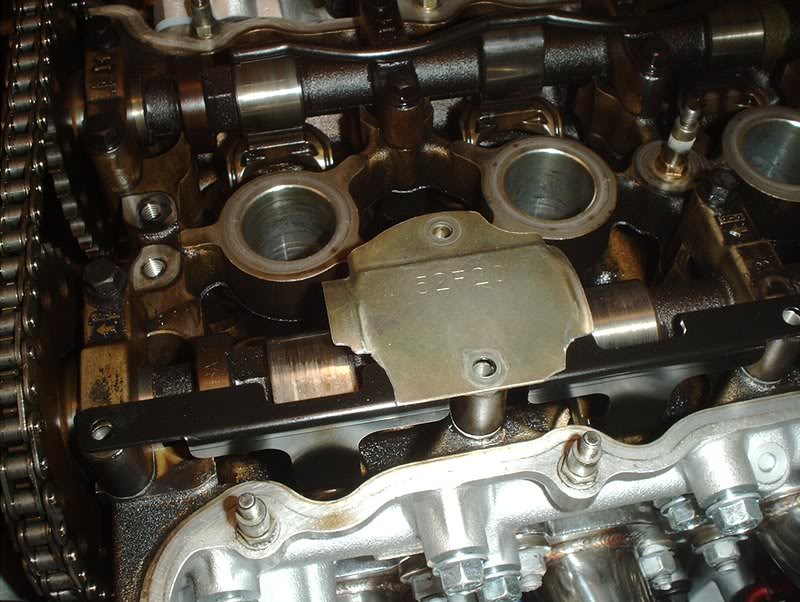
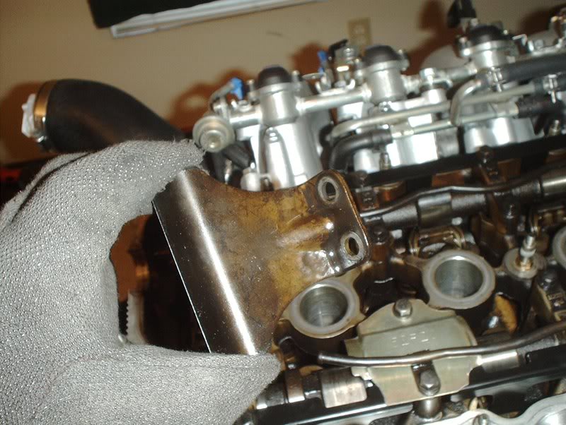
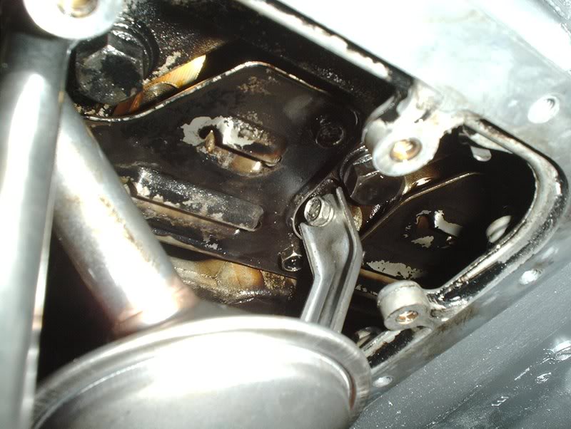
Baffle plate, I originally thought that you only had to mod this plate on the S14/S15's but I was thinking about something completely different.
It's the S14/S15 valve covers that need to be modded with a RAS install and since this is a S13 I won't go into that.

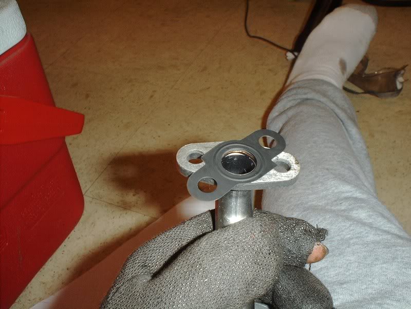
Go ahead and place the RAS into place while you have everything off. The stopper with the grooves in it is for the exhaust side while the grooveless stopper is for the intake side.
Like so.
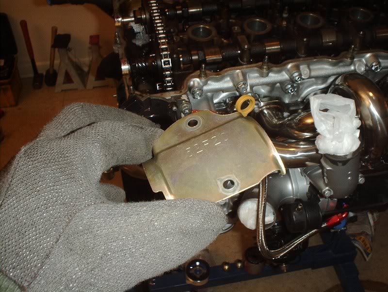
Now back to the baffle plate, as you can see here it will not sit flush on top of the RAS like it did before you removed it. You have two options here, you can either remove it or shave it with a dremel tool. I read something about oil blowby so I chose to mod it.
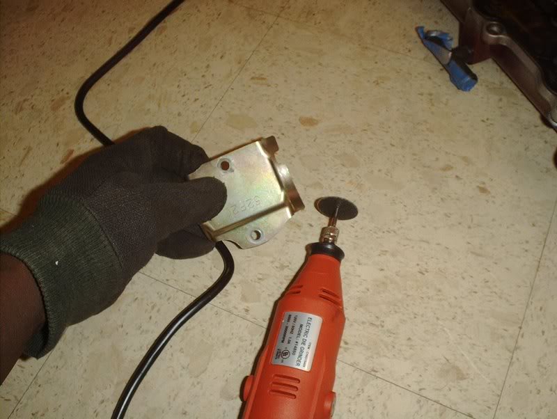
Get a dremel and a cutting tool...
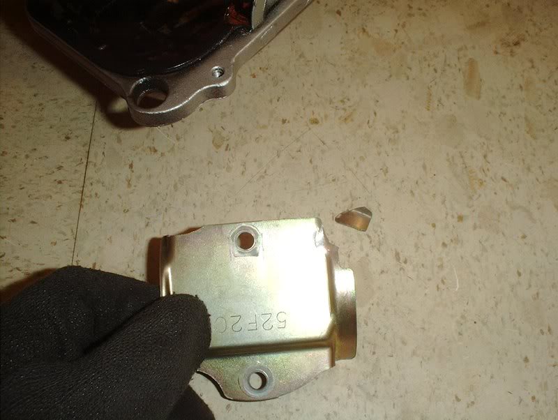
shave some metal off the two outer corners...
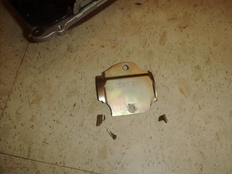
Like so.
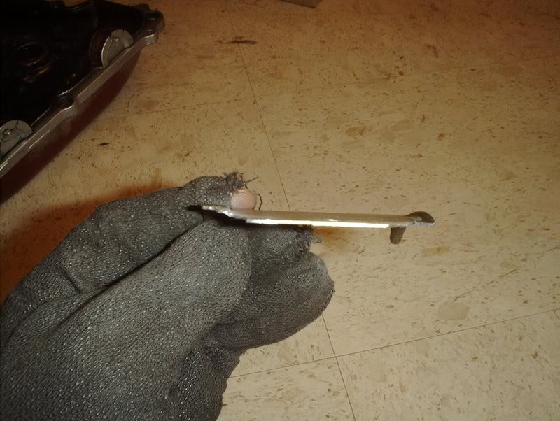
Now it's flat. Make sure you clean it up with another tool and smooth out the edges.
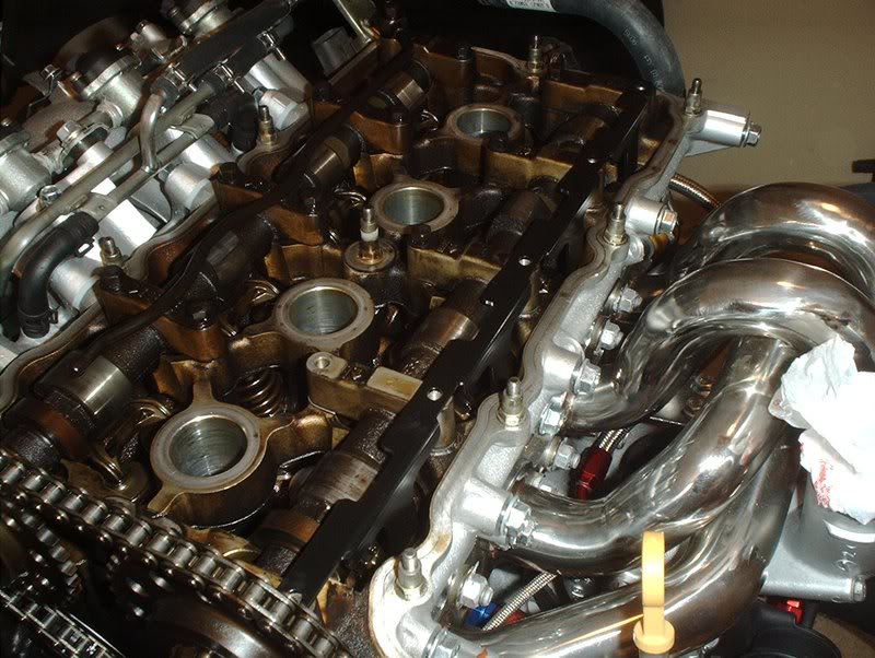
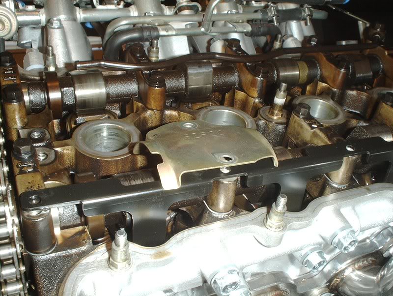
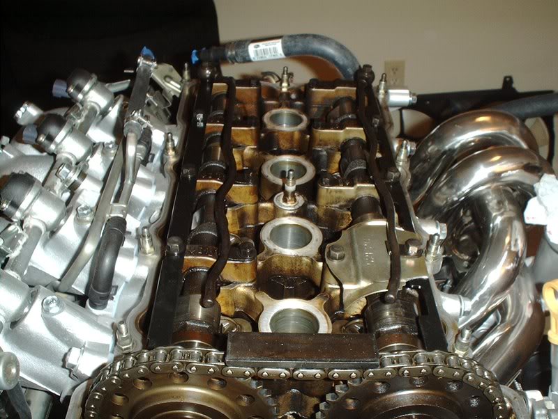
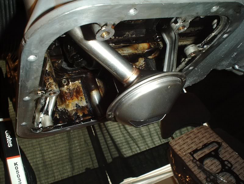
Place it on the RAS...
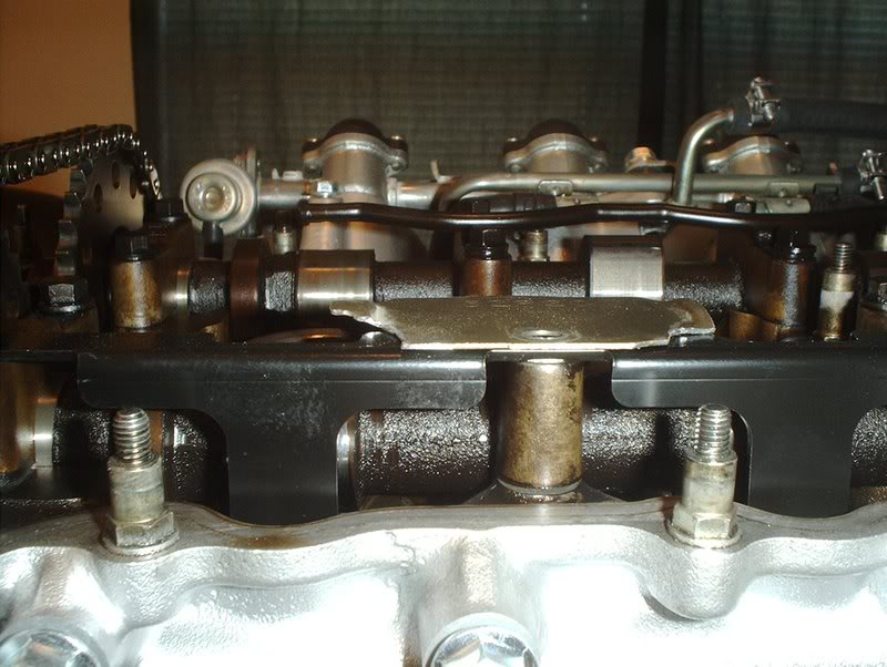
and you can see that it sits flat and will not obstruct you anymore.
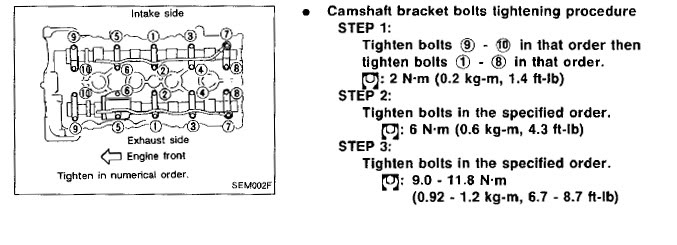
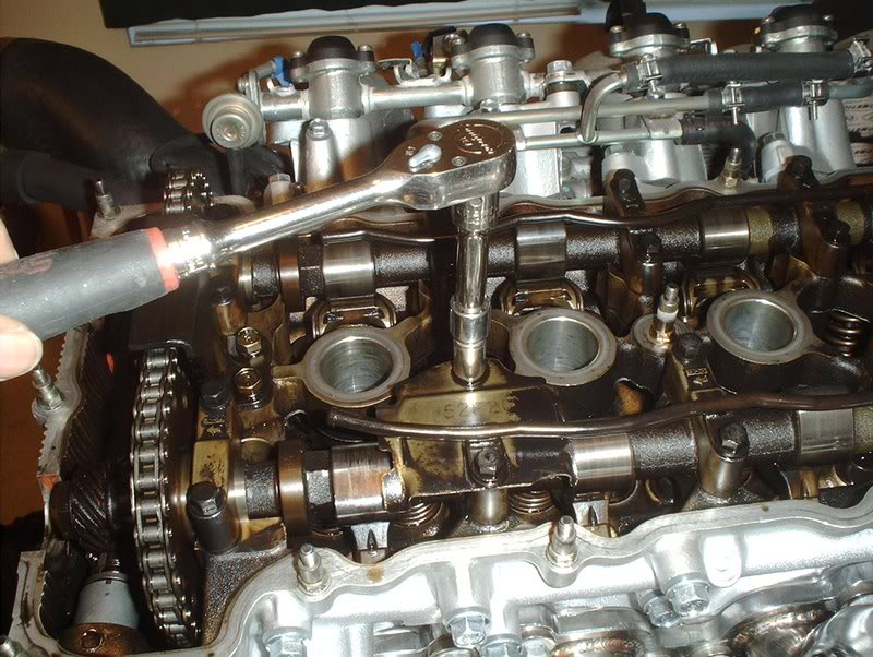
No that you have that problem fixed you can go ahead and install the oil tube, camshaft bolts/washers and torque everything down. Make sure that you follow the FSM torque and tightening specs. The camshaft bolts get torqued to 6.7-8.7ft.lbs.
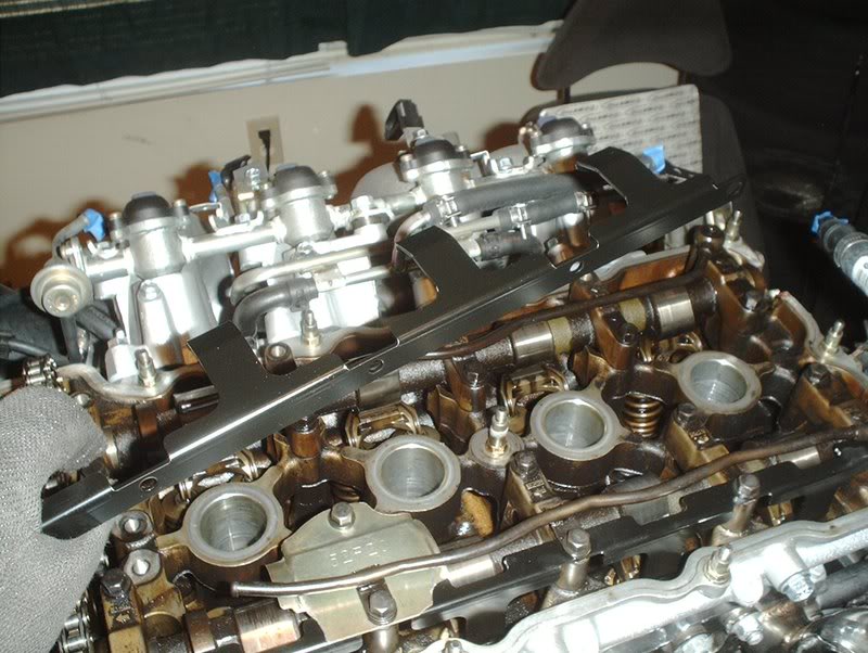
The exhaust RAS is installed, go ahead and install the intake side RAS.
Finally you need to replace the chain guard that you took off earlier.
Chain guard.
Torque to 12-14ft.lbs.
Complete, reinstall your valve cover and coil pack cover.
Tools needed:
Socket wrench
Socket extension
10mm socket
11mm socket
Dremel tool
Small flathead screwdriver
Torque wrench
Afraid of redlining or mishifting and floating a valve...get a set of rocker arm stoppers, or so they said.
Greddy rocker arm stoppers.
Start by removing your coilpack cover and valve cover. Check the FSM for the procedure on removing this as it needs to be done in a specific order.
Backside of the cover.
Internals, pretty filthy under there.
I started by removing the chain guide as you won't be able to get to the two camshaft bracket bolts near the chain guide with a socket because the guide will block you. You need a 11mm socket for this.
Off
Next, I removed the camshaft bolts. Use a 10mm socket for these.
This needs to be done in a specific order as well so follow the FSM instructions.
I cheated a little as I didn't completely remove all the inner bolts. I merely loosened them.
Be very careful when you remove the camshaft bracket bolts as there are very small washers on each of them and the bolts on the end of the oil tubes have two washers, one on the top of the oil tube and one on the bottom. MAKE SURE that you don't let any of these washers slide off and fall into your engine. This is where I used a small flathead screwdriver to snake into the washers on the oil tubes and ****** them off so they wouldn't fall in.
When you remove the bolts place them in the order that they are in the engine so you can put the same bolt back in the same place.
Baffle plate, I originally thought that you only had to mod this plate on the S14/S15's but I was thinking about something completely different.
It's the S14/S15 valve covers that need to be modded with a RAS install and since this is a S13 I won't go into that.
Go ahead and place the RAS into place while you have everything off. The stopper with the grooves in it is for the exhaust side while the grooveless stopper is for the intake side.
Like so.
Now back to the baffle plate, as you can see here it will not sit flush on top of the RAS like it did before you removed it. You have two options here, you can either remove it or shave it with a dremel tool. I read something about oil blowby so I chose to mod it.
Get a dremel and a cutting tool...
shave some metal off the two outer corners...
Like so.
Now it's flat. Make sure you clean it up with another tool and smooth out the edges.
Place it on the RAS...
and you can see that it sits flat and will not obstruct you anymore.
No that you have that problem fixed you can go ahead and install the oil tube, camshaft bolts/washers and torque everything down. Make sure that you follow the FSM torque and tightening specs. The camshaft bolts get torqued to 6.7-8.7ft.lbs.
The exhaust RAS is installed, go ahead and install the intake side RAS.
Finally you need to replace the chain guard that you took off earlier.
Chain guard.
Torque to 12-14ft.lbs.
Complete, reinstall your valve cover and coil pack cover.
Last edited by positron; 07-15-2008 at 03:45 PM.
07-15-2008, 08:36 PM
#185
Contributing Member
Thread Starter
Join Date: Sep 2002
Location: Starkville, MS.
Posts: 1,192
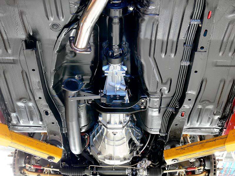
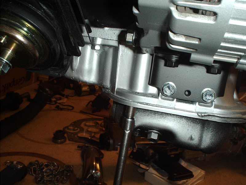
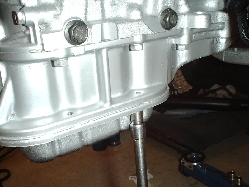
Transmission Mount
Ever since I got a downpipe I've been wondering where the bracket on the downpipe bolts to because when I was under the car, on many occasions, I didn't remember seeing anything under there that it could mount to. After a little research I finally found out where it goes.
Exhaust mount insulator part#:20610-52F00
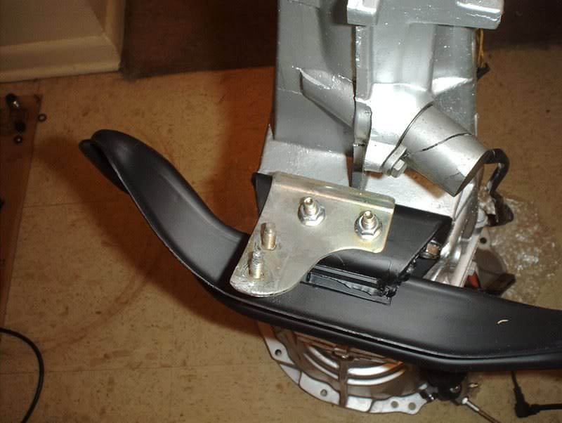
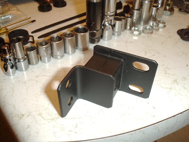
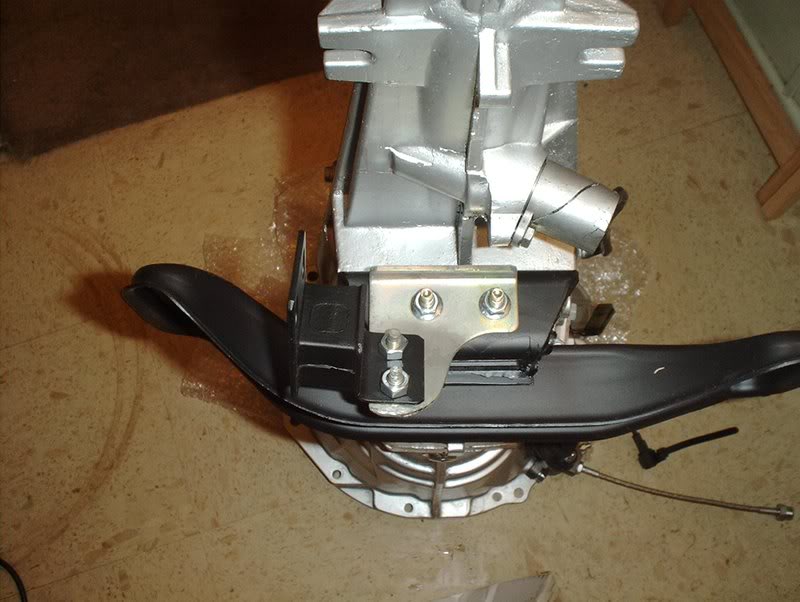
The mount goes on this bracket that attached to the transmission mount.
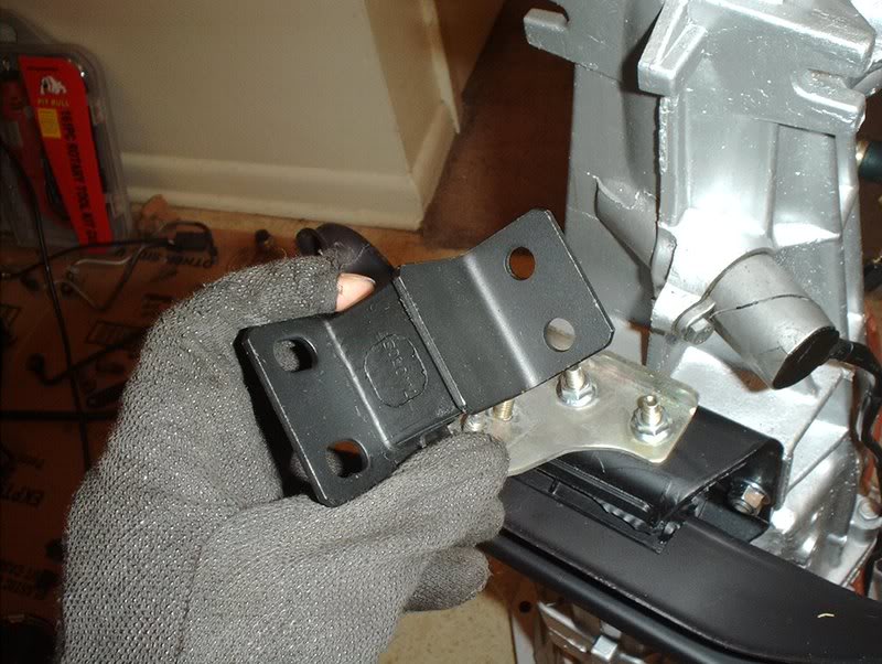
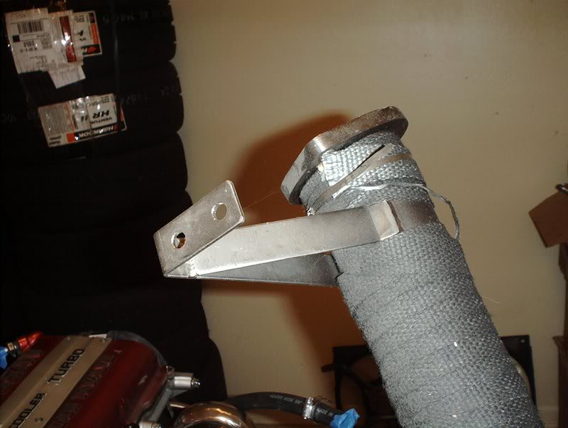
This is the bracket in question located on the downpipe.
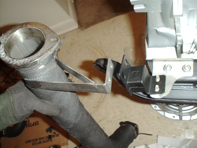
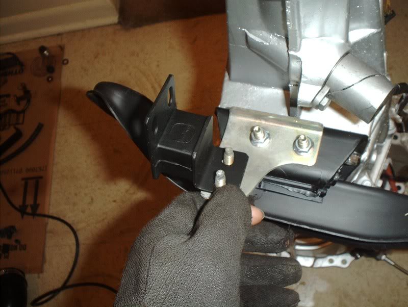
It will be connected here when the engine is swapped in.
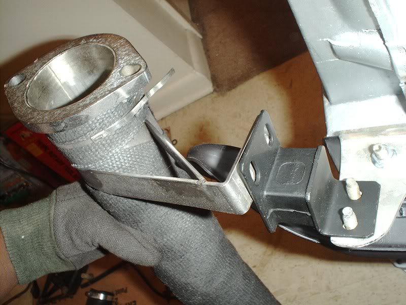
If you need nuts then use M8-1,25 and a M8 short bolt for the downpipe.
The finished product will look like this.
Exhaust mount insulator part#:20610-52F00
The mount goes on this bracket that attached to the transmission mount.
This is the bracket in question located on the downpipe.
It will be connected here when the engine is swapped in.
If you need nuts then use M8-1,25 and a M8 short bolt for the downpipe.
The finished product will look like this.
07-15-2008, 08:37 PM
#186
Contributing Member
Thread Starter
Join Date: Sep 2002
Location: Starkville, MS.
Posts: 1,192
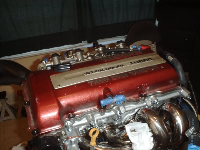
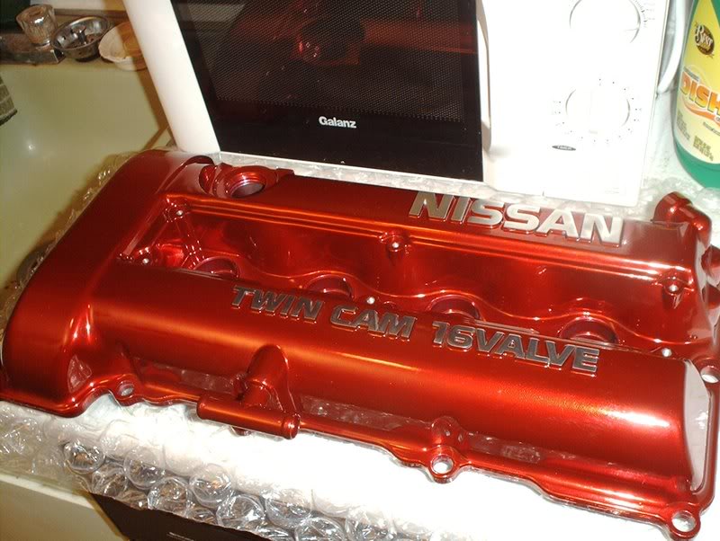
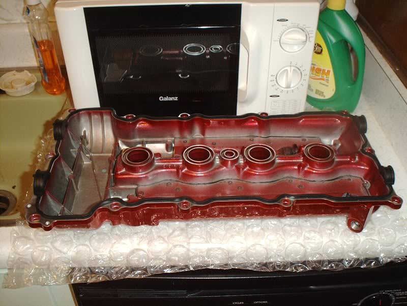
Valvecover
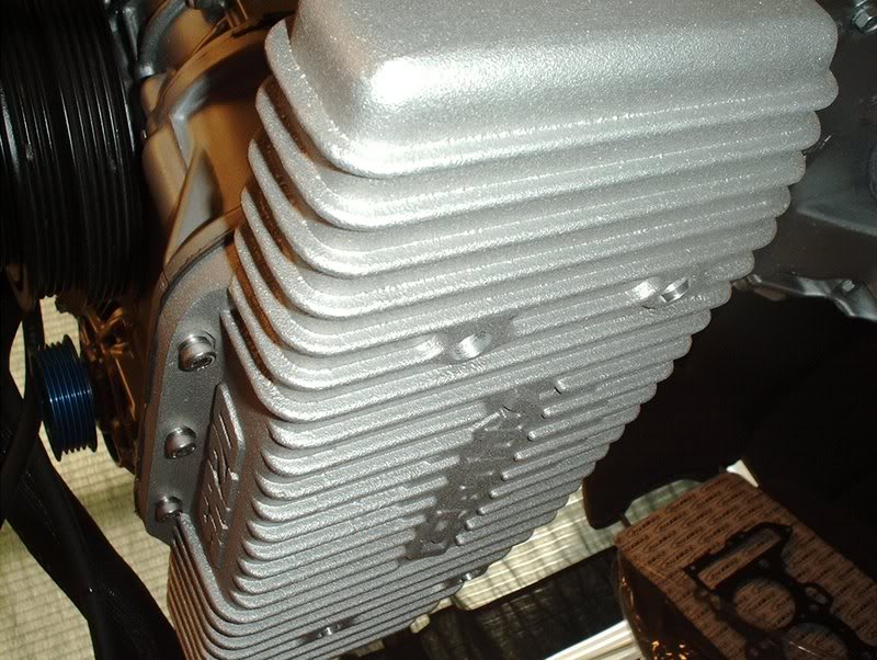
I finally broke down and got a valvecover, wanted a redtop and when it came time to ship out they email me and tell me this..."Thank you for your order with us. Unfortunately, the redtop valve cover has been out of stock from nissan for quite a few months and there's no sign of them coming back in." So apparently Nissan isn't getting out anymore redtop valvecovers at all because I checked the next seven or so top Nissan parts websites and they all said the same thing. So Phase2 gave me the option of buying a unpainted cover and having it powdercoated which I did.
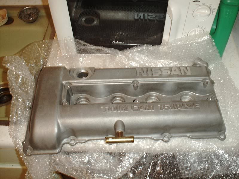
S13 SR20DET Valvecover part#:13264-52F5B
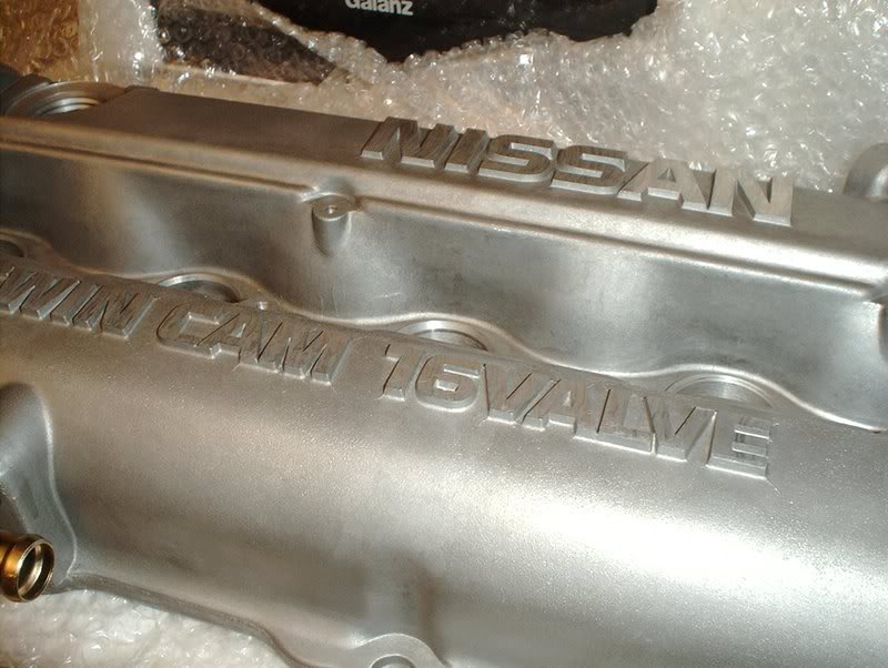
I'm going to send it out to Bonehead Performance and have it powdercoated some shade of red, probably "anodized red".
Could have just powdercoated the old cover but it's got a chip on it that I'm raising the people's eyebrow at.
TO BE CONTINUED.....
S13 SR20DET Valvecover part#:13264-52F5B
I'm going to send it out to Bonehead Performance and have it powdercoated some shade of red, probably "anodized red".
Could have just powdercoated the old cover but it's got a chip on it that I'm raising the people's eyebrow at.
TO BE CONTINUED.....
08-05-2008, 04:20 PM
#188
Contributing Member
Thread Starter
Join Date: Sep 2002
Location: Starkville, MS.
Posts: 1,192
Fuel Lines
Got a set of fuel lines in.
Tools needed:
Screwdriver
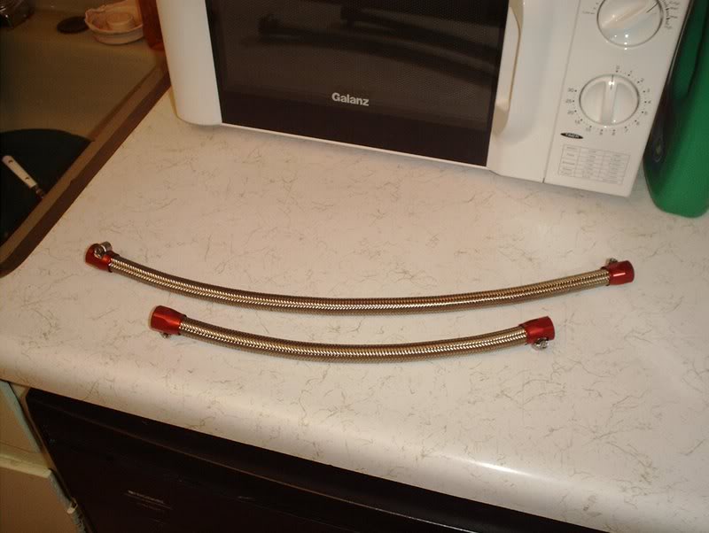
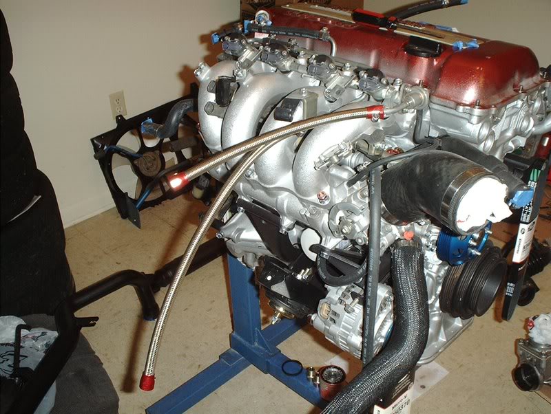
Got a set of stainless steel fuel lines in to use instead of the 5/16" rubber hose.
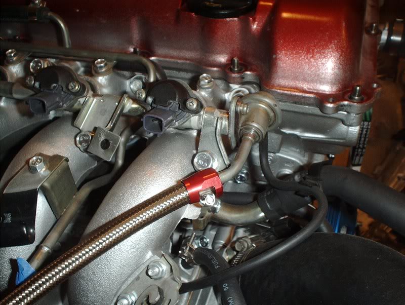
The longer line goes from the fuel pressure regulator to the hardline.
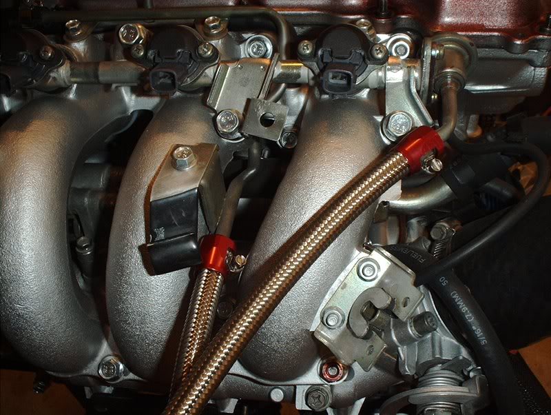
The shorter line goes from the manifold here to the hardline.
SIDENOTE: Should a set of Altima fans with a fan controller be wired up for high speed or low speed?
Tools needed:
Screwdriver
Got a set of stainless steel fuel lines in to use instead of the 5/16" rubber hose.
The longer line goes from the fuel pressure regulator to the hardline.
The shorter line goes from the manifold here to the hardline.
SIDENOTE: Should a set of Altima fans with a fan controller be wired up for high speed or low speed?
08-07-2008, 02:59 PM
#189
Contributing Member
Thread Starter
Join Date: Sep 2002
Location: Starkville, MS.
Posts: 1,192
Oil pan
My new oil pan comes in today so I spent some time removing the old one.
Tools needed:
Socket wrench
Socket extension
10mm socket
12mm socket
Rubber mallet
Paint scraper
Paper towels
Trash bag
Soap( to wash mouth out...you'll see why later!)
OEM Oil pan, I wanted to swap it out just for piece of mind.
Get a 10mm socket, you need to remove the oil pan bolts in a specific order so refer to the FSM but it goes as follows for a S13 SR20.
The front middle bolt,
the rear middle bolt,
the front right bolt,
the rear right bolt,
the front left bolt,
the rear left bolt,
the front right side bolt,
the front left side bolt,
the rear right side bolt
and finally the rear left side bolt.
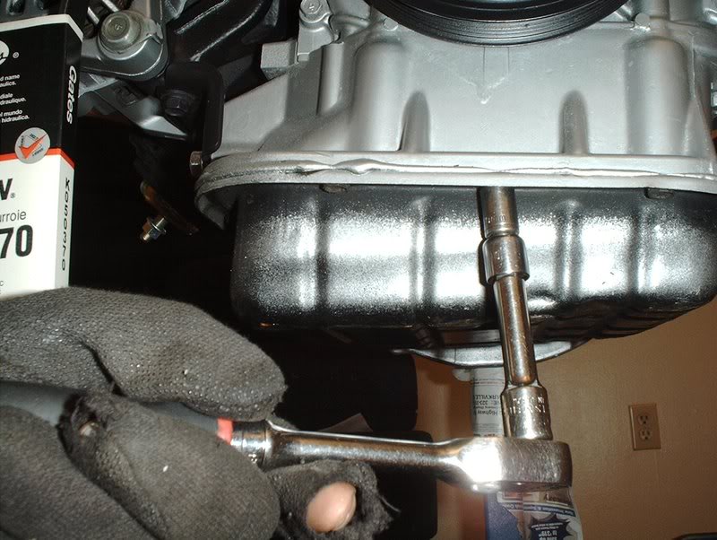
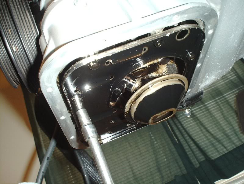
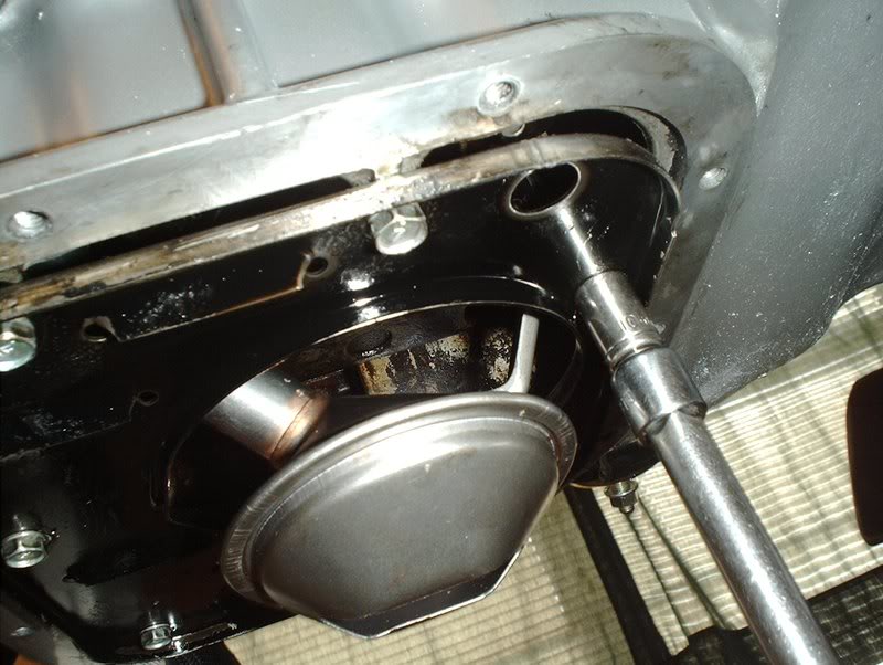
Time for the oil pan removal.
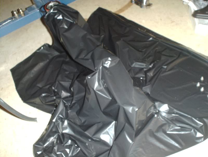
I didn't have a drain pan for the engine stand so I laid down a garbage bag.
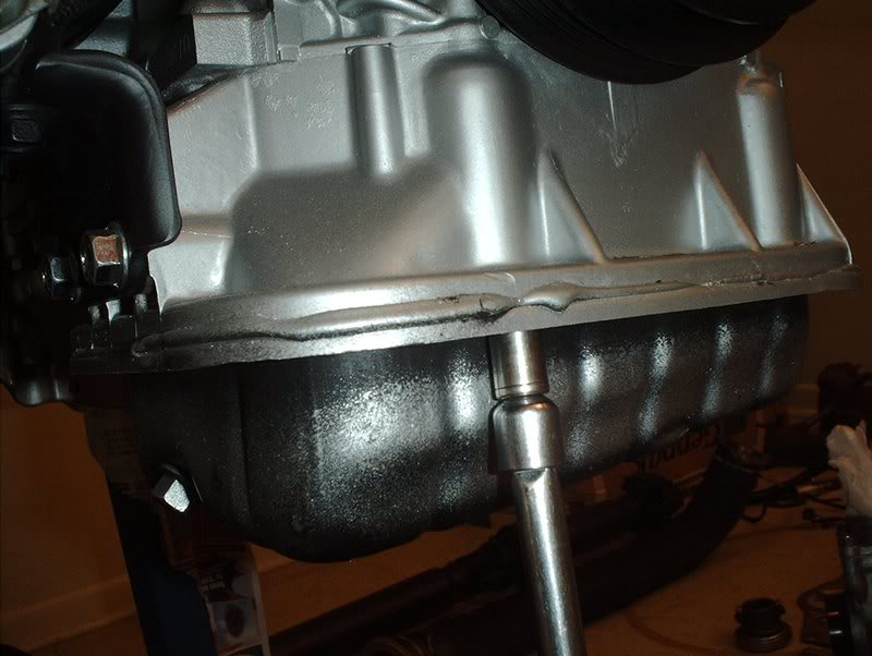
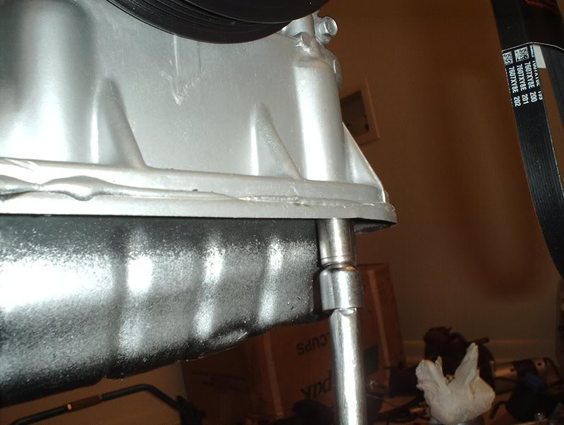
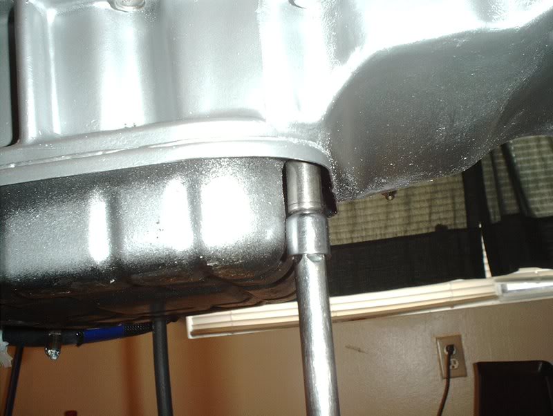
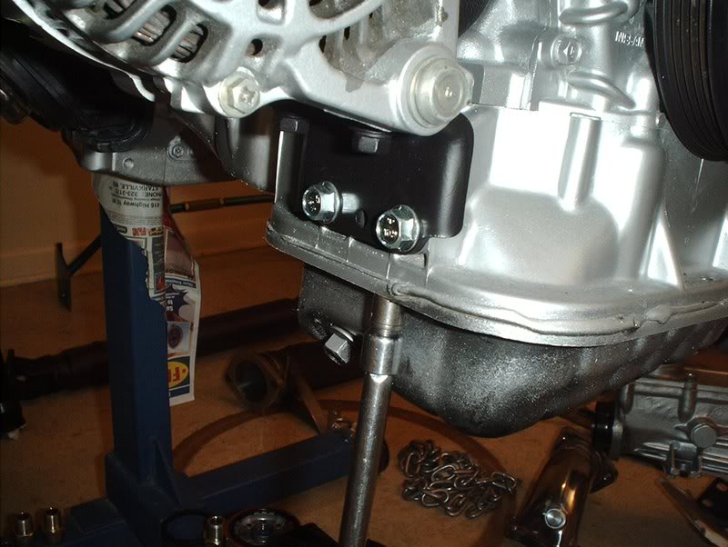
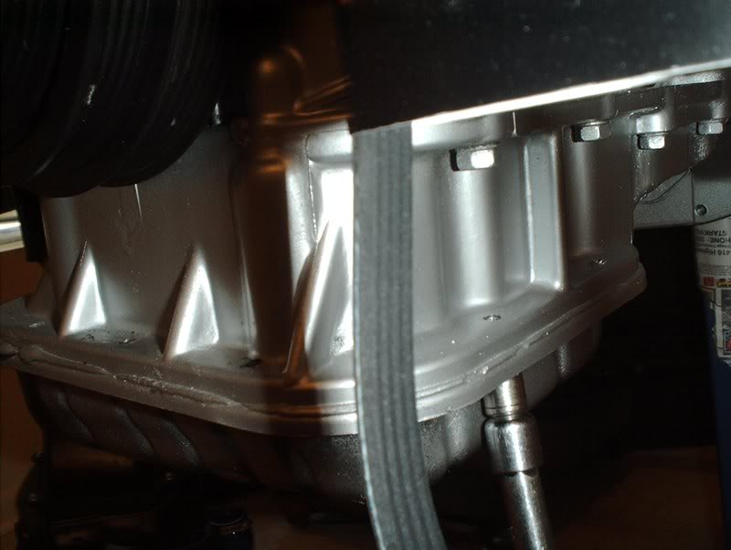
Now you need to bust the gasket on the pan loose so you can remove the pan itself. I was a little worried about this part when it came to possibly scraping up the oil pan mating surface.
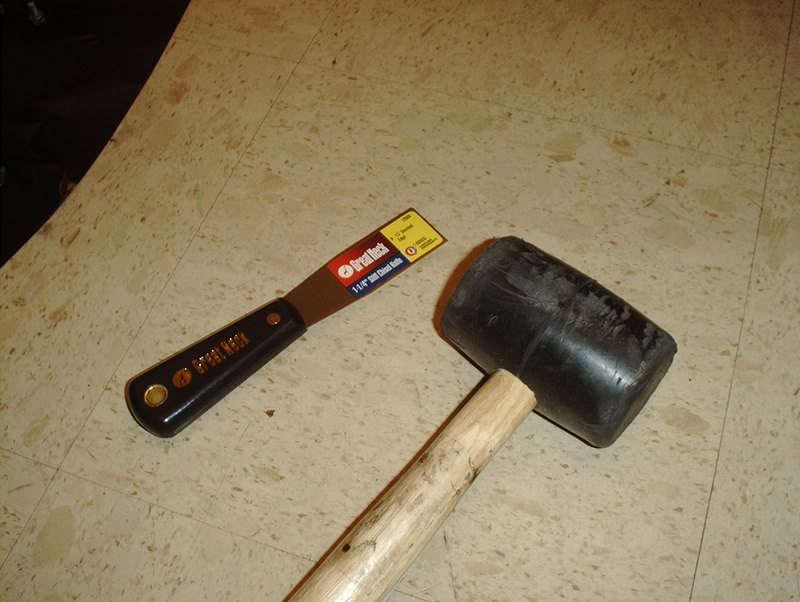
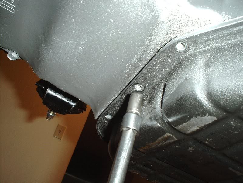
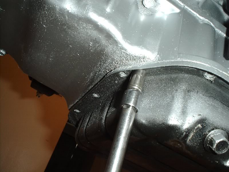
Use a rubber mallet and a paint scraper or some equivalent.
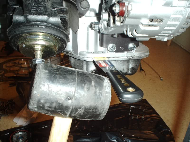
Insert the scraper into the pan by lightly tapping it. You will feel it move inward once the gasket is broken but take care not to scrape up the aluminum mating surface.
Once you get it in, then hammer and chisel the scraper around by tapping it on the side. Don't make the mistake that I did. I tapped all the gasket down to the last inch without holding the oil pan and...
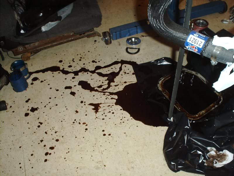
the pan drops and oil goes everywhere...idiot!!!
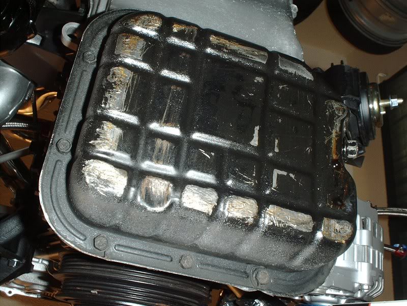
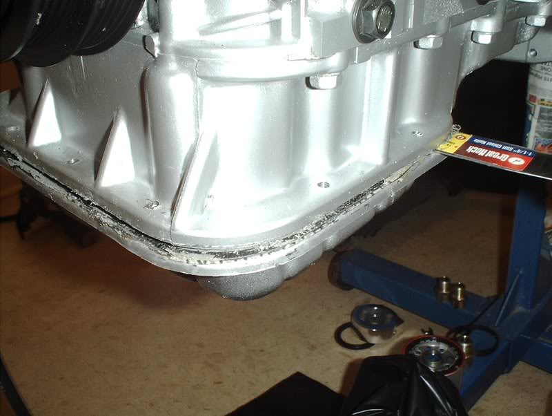
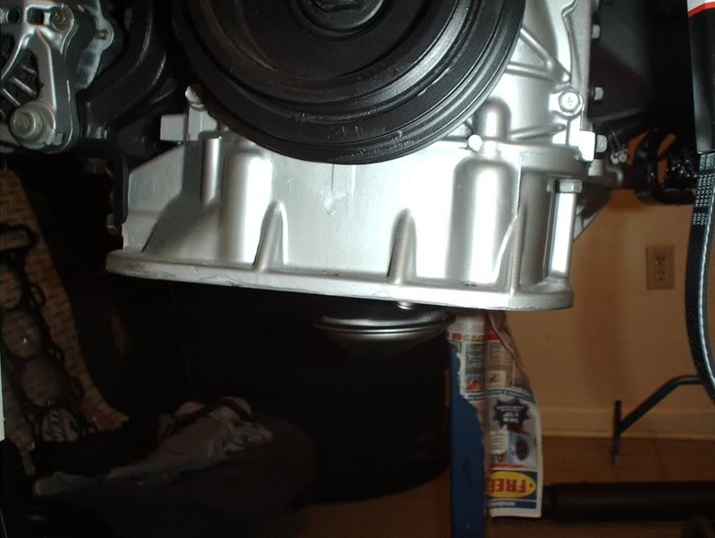
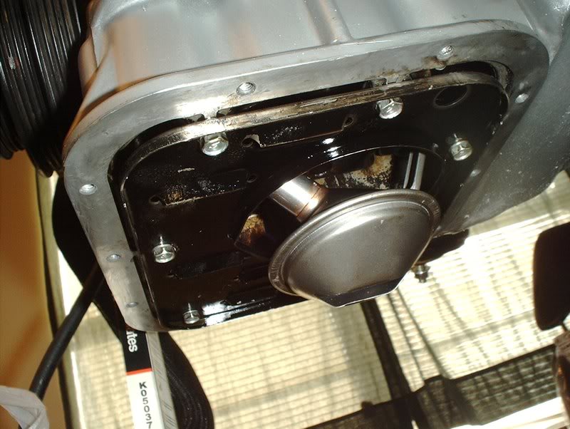
Oil pan removed
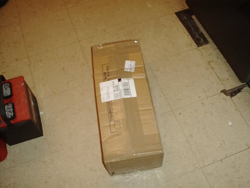
Right in the middle of this removal, the UPS man drops off my new oil pan so perfect timing indeed!
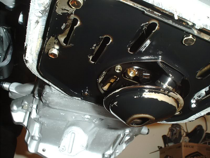
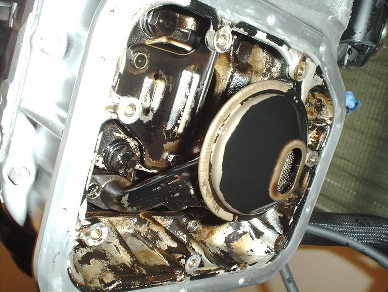
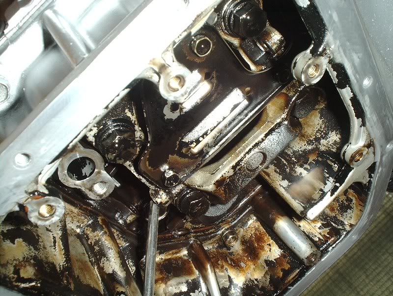
With the pan off you can see the internals, baffle plate, oil strainer, etc!
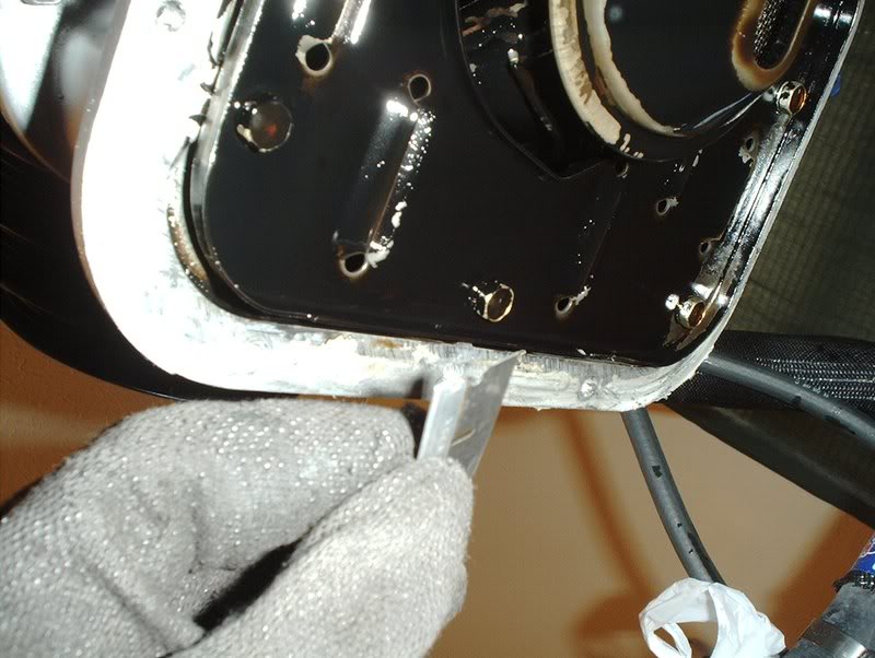
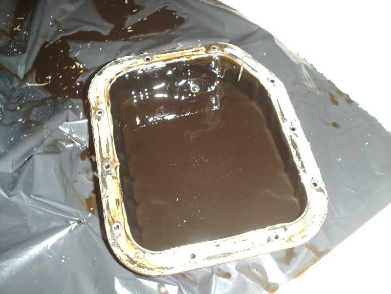
I used a razorblade to remove the old gasket from the surface.
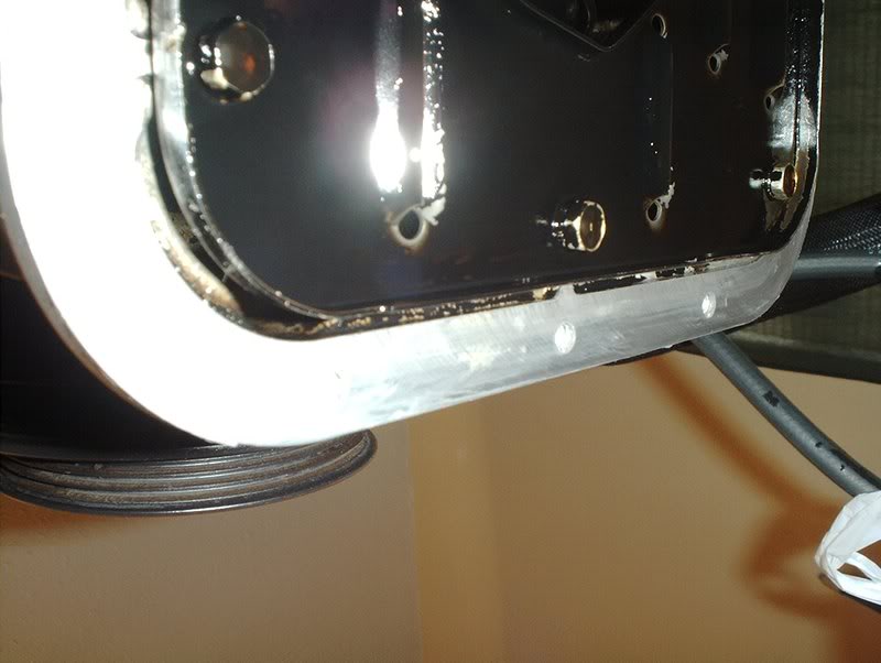
Cleaned it up, for the last bits of gasket just use the world's best scraper, your fingernails.
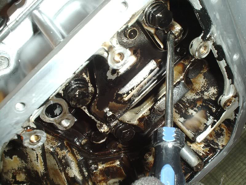
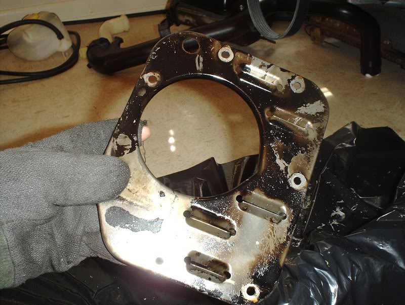
I also decided to swap out the oil strainer while I was at it. Use a 10mm socket to remove the baffle plate.
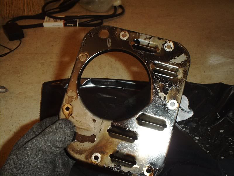
Baffle plate.
Removed.
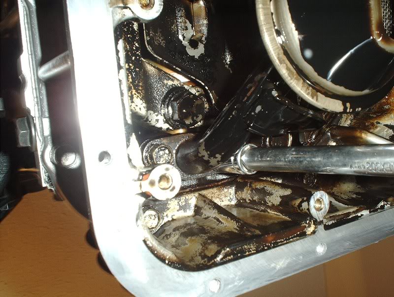
Use a 12mm socket to remove 2 bolts holding the strainer in.
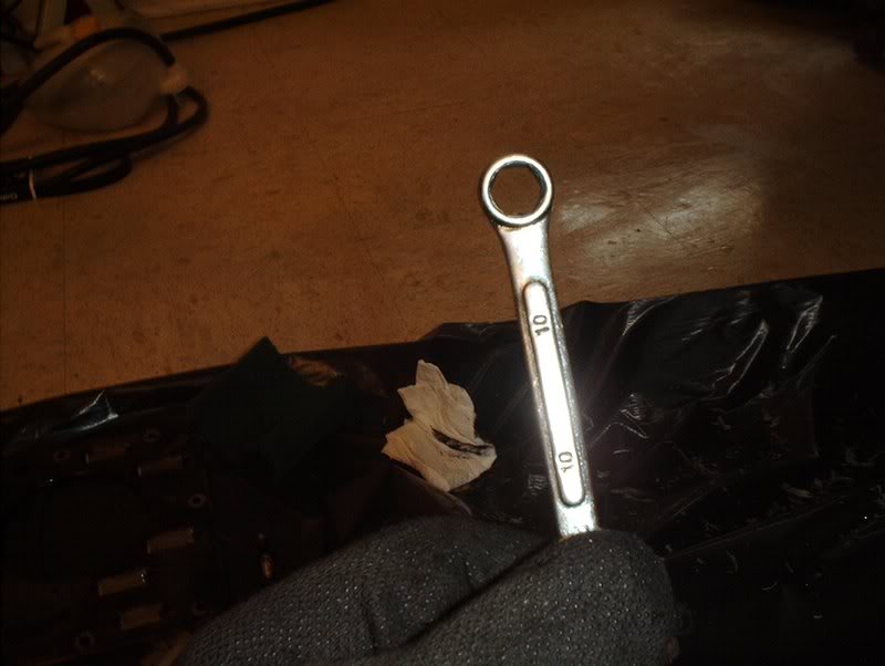
There is a small bolt holding the strainer bracket in also. You can't get a socket in this cramped space so use a 10mm box wrench to remove it.
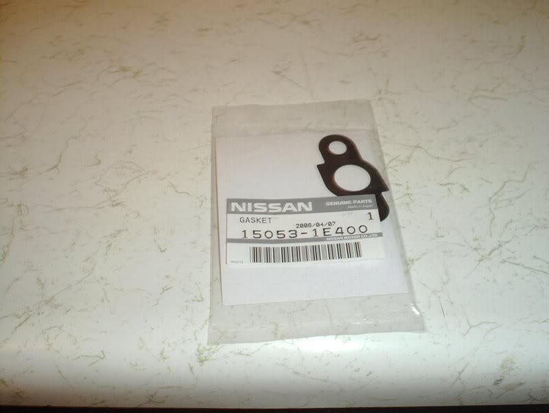
OEM Oil Strainer Gasket part#: 15053-1E400.
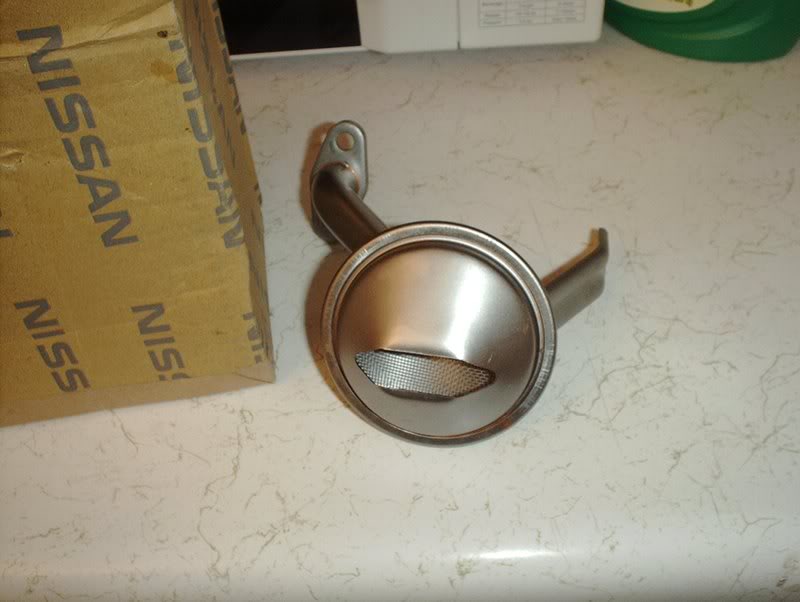
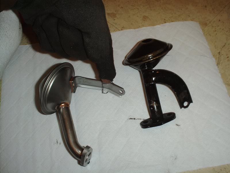
OEM S14 Oil Strainer part#: 15050-65F01.
I decided to use the S14 strainer because they say that it is a upgrade and picks up oil better because of the extra slotting on the sides...
as you can see here.
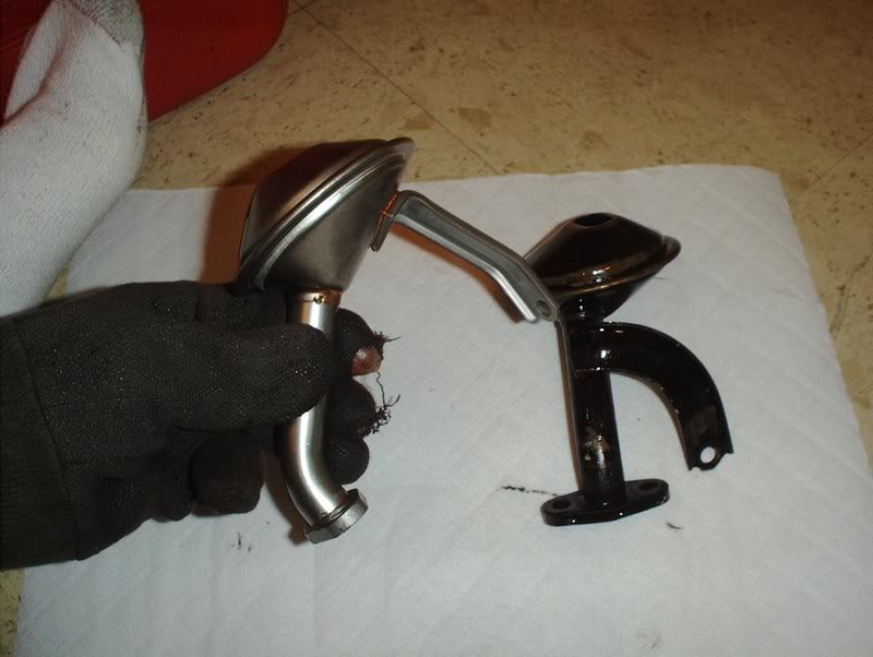
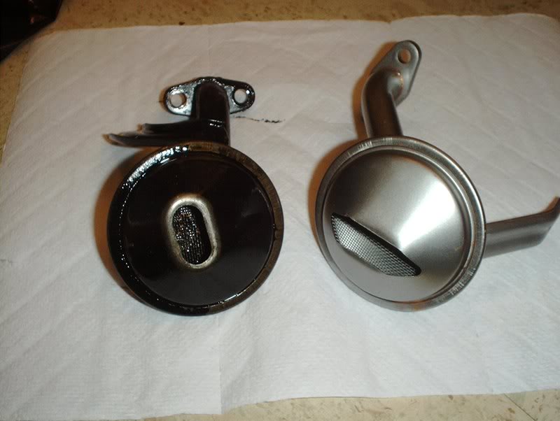
S14 strainer vs. S13 strainer.
I was looking at these strainers and realized that the support brackets were in different places and thought that would be a problem because I wouldn't be able to bolt this bracket in but, after some testing, I found out that it wouldn't be a problem after all.
The S13 strainer bracket bolts here...
while the S14 bracket can be bolted here.
Take the gasket and place it on the strainer.
Bolt the strainer in but keep it loose for now...and this is where the soap to wash out your mouth comes into play...
because getting this bolt in was a PITA! I cursed NISSAN and everyone who works for them but I finally got it on and tightened.
The strainer is on. Don't forget to tighten and torque the strainer bolts to 12-14flt.lbs. I just tightened the strainer bracket.
I'm gonna have to wrap this up some other time, I gotta go to work.
Tonight...you!
TO BE CONTINUED!!!
Tools needed:
Socket wrench
Socket extension
10mm socket
12mm socket
Rubber mallet
Paint scraper
Paper towels
Trash bag
Soap( to wash mouth out...you'll see why later!)
OEM Oil pan, I wanted to swap it out just for piece of mind.
Get a 10mm socket, you need to remove the oil pan bolts in a specific order so refer to the FSM but it goes as follows for a S13 SR20.
The front middle bolt,
the rear middle bolt,
the front right bolt,
the rear right bolt,
the front left bolt,
the rear left bolt,
the front right side bolt,
the front left side bolt,
the rear right side bolt
and finally the rear left side bolt.
Time for the oil pan removal.
I didn't have a drain pan for the engine stand so I laid down a garbage bag.
Now you need to bust the gasket on the pan loose so you can remove the pan itself. I was a little worried about this part when it came to possibly scraping up the oil pan mating surface.
Use a rubber mallet and a paint scraper or some equivalent.
Insert the scraper into the pan by lightly tapping it. You will feel it move inward once the gasket is broken but take care not to scrape up the aluminum mating surface.
Once you get it in, then hammer and chisel the scraper around by tapping it on the side. Don't make the mistake that I did. I tapped all the gasket down to the last inch without holding the oil pan and...
the pan drops and oil goes everywhere...idiot!!!
Oil pan removed
Right in the middle of this removal, the UPS man drops off my new oil pan so perfect timing indeed!
With the pan off you can see the internals, baffle plate, oil strainer, etc!
I used a razorblade to remove the old gasket from the surface.
Cleaned it up, for the last bits of gasket just use the world's best scraper, your fingernails.
I also decided to swap out the oil strainer while I was at it. Use a 10mm socket to remove the baffle plate.
Baffle plate.
Removed.
Use a 12mm socket to remove 2 bolts holding the strainer in.
There is a small bolt holding the strainer bracket in also. You can't get a socket in this cramped space so use a 10mm box wrench to remove it.
OEM Oil Strainer Gasket part#: 15053-1E400.
OEM S14 Oil Strainer part#: 15050-65F01.
I decided to use the S14 strainer because they say that it is a upgrade and picks up oil better because of the extra slotting on the sides...
as you can see here.
S14 strainer vs. S13 strainer.
I was looking at these strainers and realized that the support brackets were in different places and thought that would be a problem because I wouldn't be able to bolt this bracket in but, after some testing, I found out that it wouldn't be a problem after all.
The S13 strainer bracket bolts here...
while the S14 bracket can be bolted here.
Take the gasket and place it on the strainer.
Bolt the strainer in but keep it loose for now...and this is where the soap to wash out your mouth comes into play...
because getting this bolt in was a PITA! I cursed NISSAN and everyone who works for them but I finally got it on and tightened.
The strainer is on. Don't forget to tighten and torque the strainer bolts to 12-14flt.lbs. I just tightened the strainer bracket.
I'm gonna have to wrap this up some other time, I gotta go to work.
Tonight...you!
TO BE CONTINUED!!!
 08-09-2008, 04:50 PM
#191
Contributing Member
Thread Starter
Join Date: Sep 2002
Location: Starkville, MS.
Posts: 1,192
Oil pan Continued
I finished installing my oil pan today.
Tools needed:
Socket wrench
Socket extension
10mm socket
Allen wrench
Phillips head screwdriver
Oil pan gasket
Razor
Picking back up where I last left off...
I need to reinstall the baffle plate.
Use a socket wrench and 10mm socket to put the bolts back in. Torque to 4.7 to 5.5ft.lbs.
Done here.
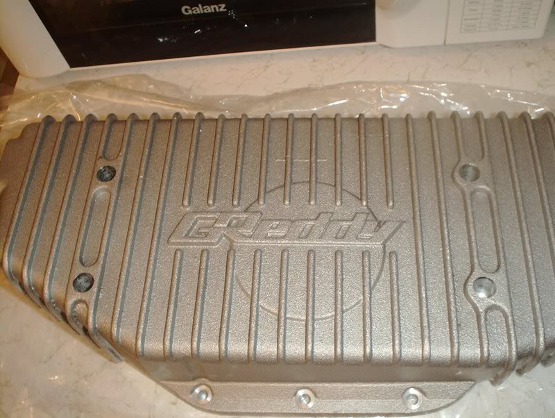
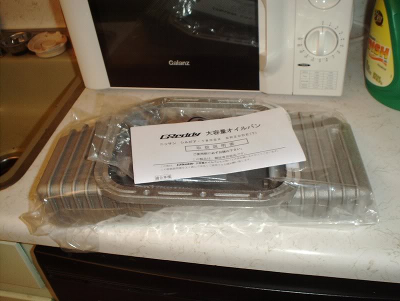
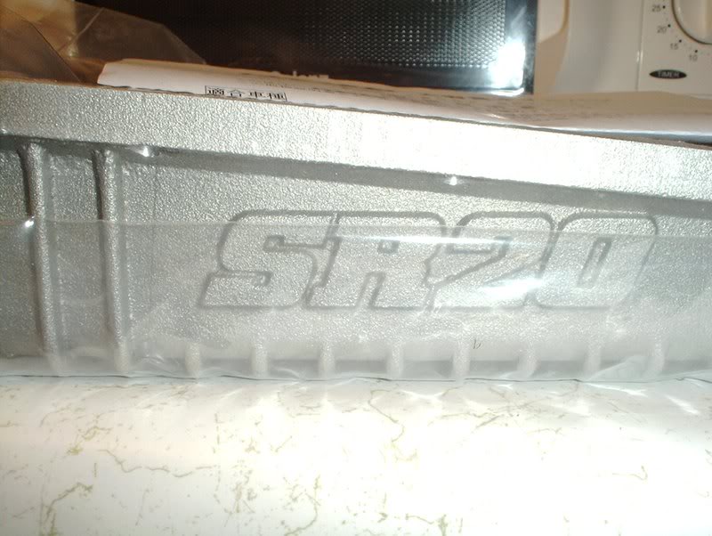
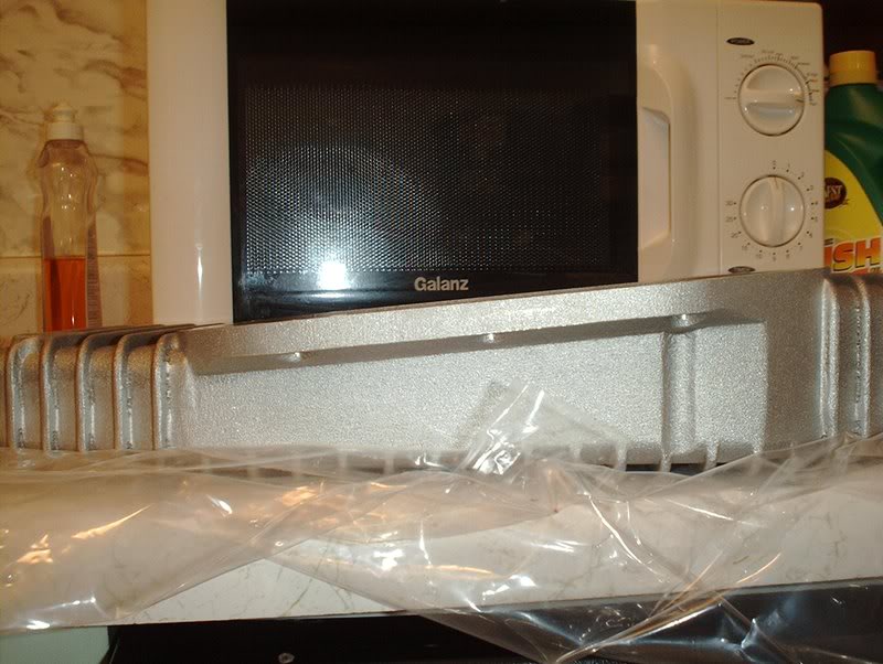
Greddy oil pan.
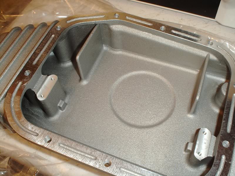
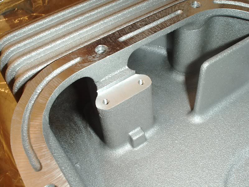
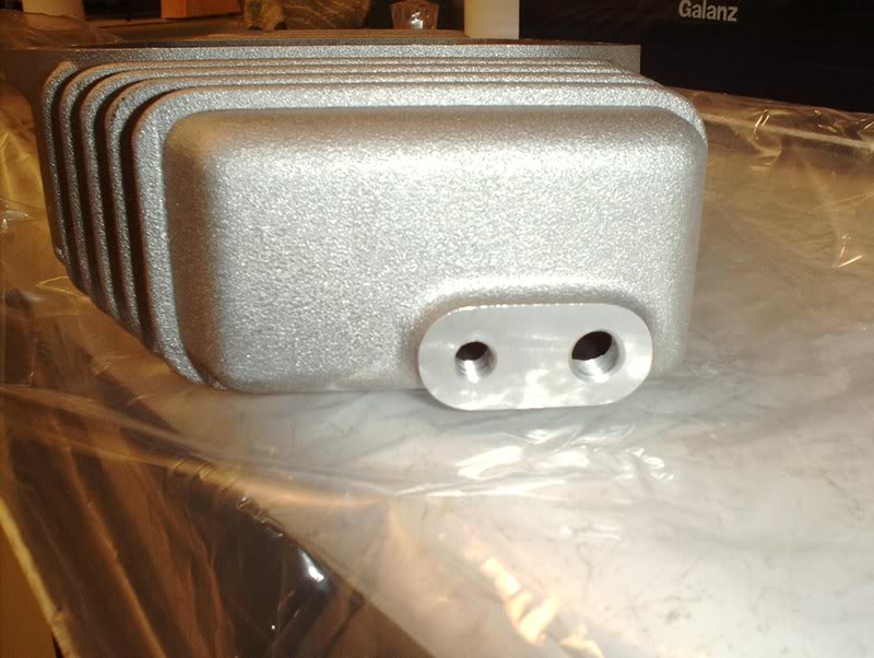
These are the ports for the oil drain plug and optional oil temperature sensor.
I'm going to get a oil temp guage but for now I'll close this up.
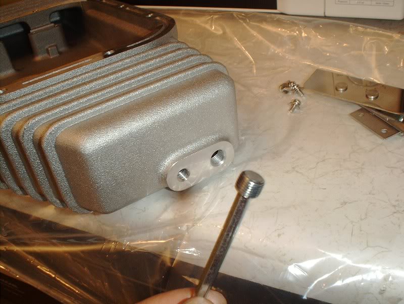
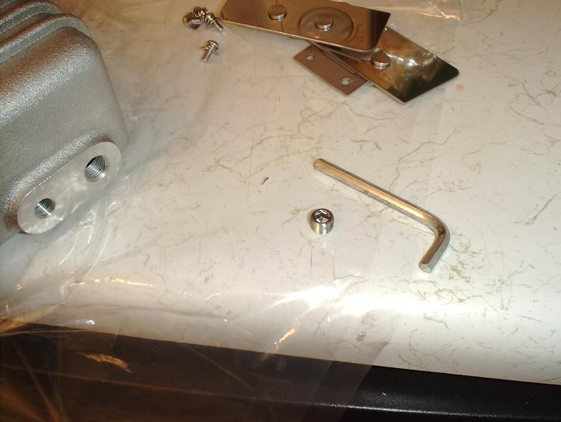
Just use a allen wrench, which size I'm not sure...
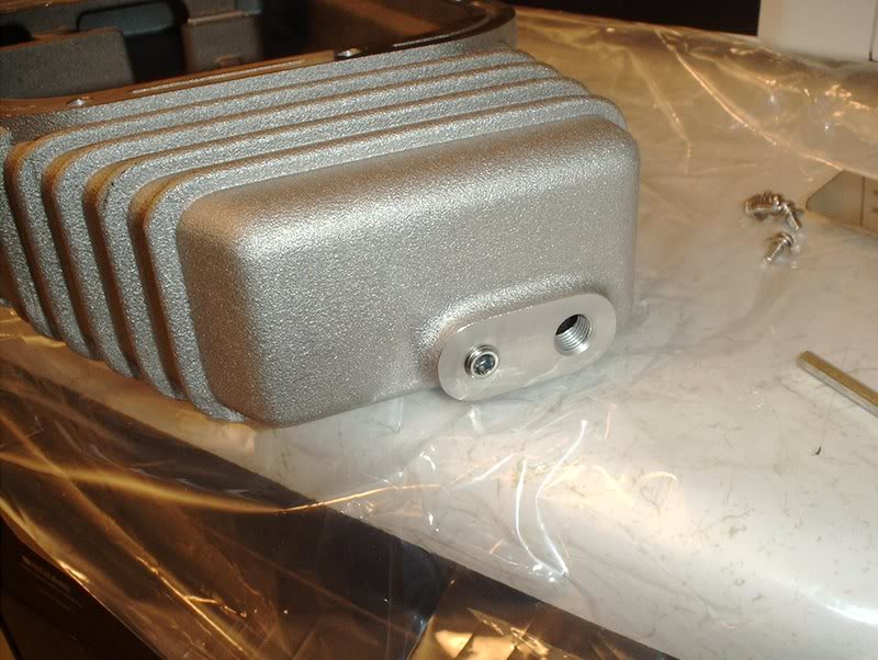
to put this plug in.
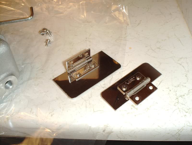
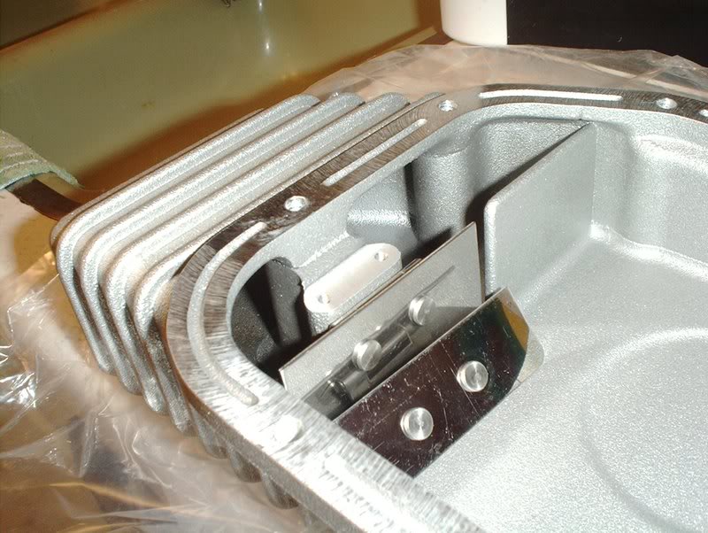
Baffle plates. The instructions for this oil pan are all in Japanese so I had to look at the pictures and guesstimate where everything goes.
From what I've read these plates keep the oil centered in the pan during hard cornering hence the swiveling hinges.
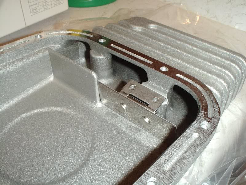
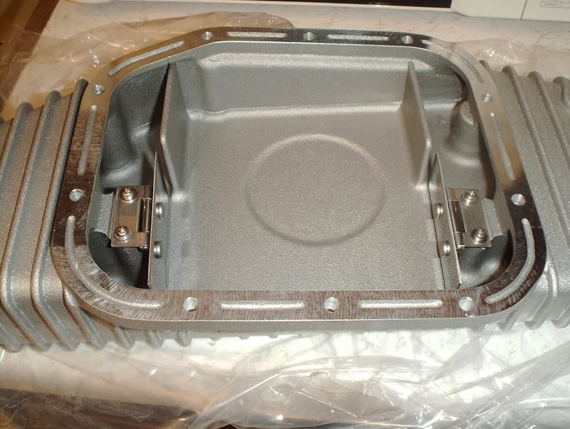
You'll notice that one baffle plate is taller than the other...
just as one side of the oil pan is taller than the other...
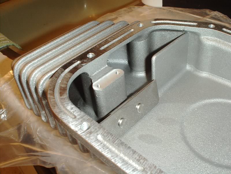
so they'll really only fit on one way.
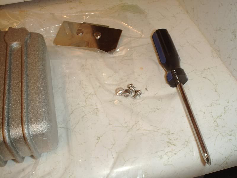
Make sure you have the hardware.
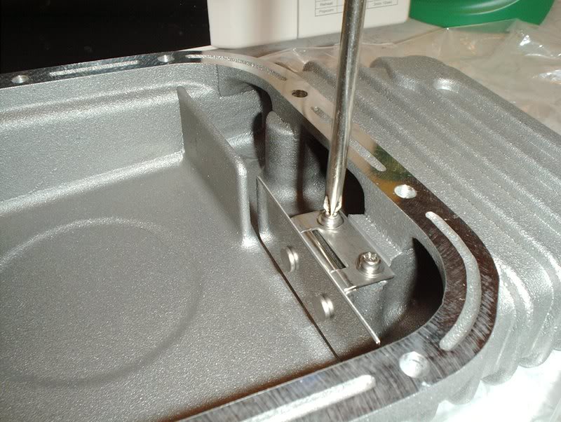
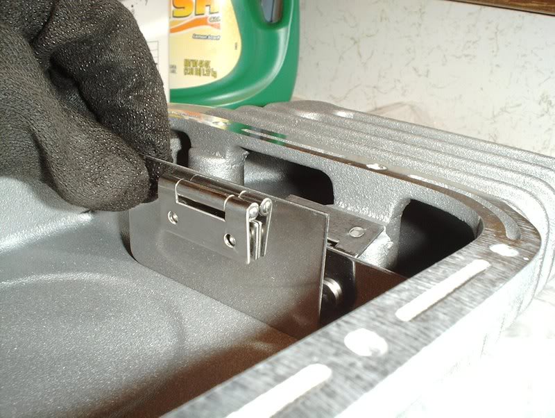
Use a phillipshead screwdriver to install the plates.
Done.
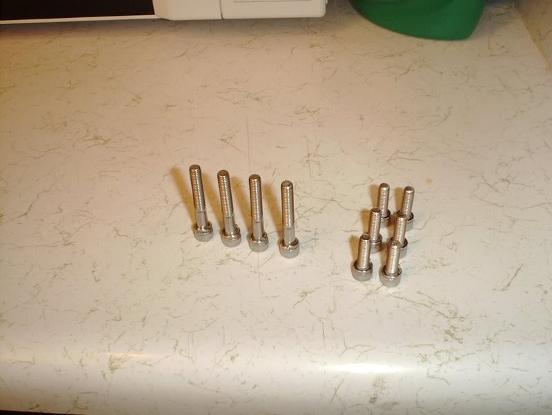
Make sure you have the hardware for the oil pan.
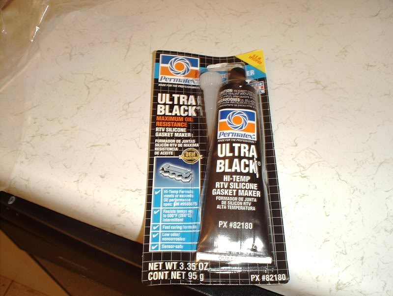
I used Ultra Black for the gasket.
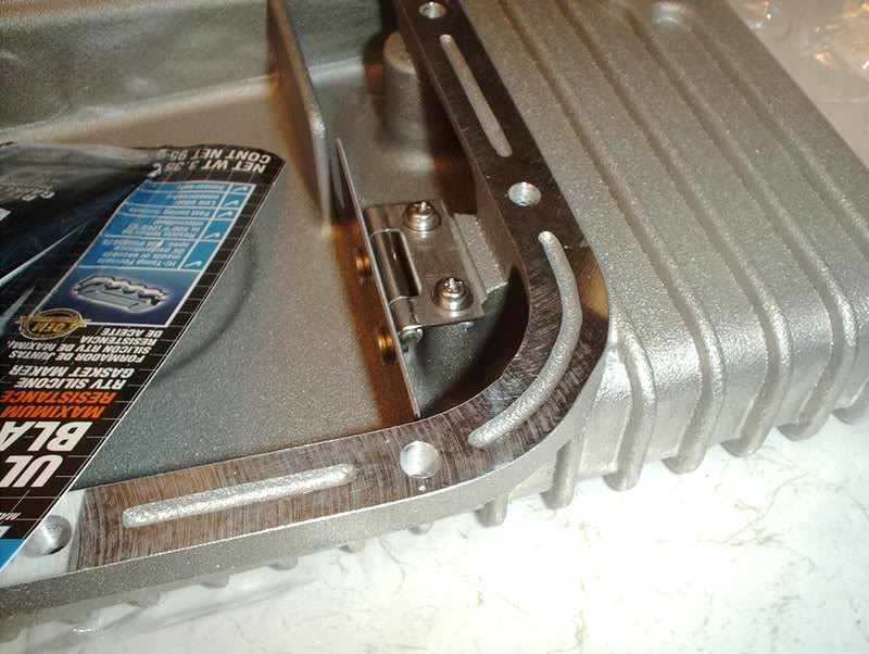
Greddy put grooves in the pan to show you how much of a bead of gasket to use and where to put it...sweet attention to detail!
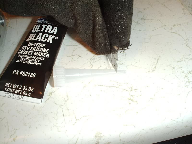
Cut the tip at the second mark and place your gasket around in a continuous bead and install the pan within 5 minutes or the gasket will start to cure. Have your bolts and allen wrench on standby. I forgot to mention that these oil pan bolts use a allen wrench.
I also don't have the torque specs...
but you couldn't torque allen wrenches anyway( on second thought you could but I don't have that tool/socket)...
so I just tightened them down "real good". I speak good English don't I?
I guess you would just use the OEM pan's torque specs which are 4.7-5.5ft.lbs.
Tools needed:
Socket wrench
Socket extension
10mm socket
Allen wrench
Phillips head screwdriver
Oil pan gasket
Razor
Picking back up where I last left off...
I need to reinstall the baffle plate.
Use a socket wrench and 10mm socket to put the bolts back in. Torque to 4.7 to 5.5ft.lbs.
Done here.
Greddy oil pan.
These are the ports for the oil drain plug and optional oil temperature sensor.
I'm going to get a oil temp guage but for now I'll close this up.
Just use a allen wrench, which size I'm not sure...
to put this plug in.
Baffle plates. The instructions for this oil pan are all in Japanese so I had to look at the pictures and guesstimate where everything goes.
From what I've read these plates keep the oil centered in the pan during hard cornering hence the swiveling hinges.
You'll notice that one baffle plate is taller than the other...
just as one side of the oil pan is taller than the other...
so they'll really only fit on one way.
Make sure you have the hardware.
Use a phillipshead screwdriver to install the plates.
Done.
Make sure you have the hardware for the oil pan.
I used Ultra Black for the gasket.
Greddy put grooves in the pan to show you how much of a bead of gasket to use and where to put it...sweet attention to detail!
Cut the tip at the second mark and place your gasket around in a continuous bead and install the pan within 5 minutes or the gasket will start to cure. Have your bolts and allen wrench on standby. I forgot to mention that these oil pan bolts use a allen wrench.
I also don't have the torque specs...
but you couldn't torque allen wrenches anyway( on second thought you could but I don't have that tool/socket)...
so I just tightened them down "real good". I speak good English don't I?
I guess you would just use the OEM pan's torque specs which are 4.7-5.5ft.lbs.
08-12-2008, 03:19 PM
#193
Contributing Member
Thread Starter
Join Date: Sep 2002
Location: Starkville, MS.
Posts: 1,192
Fan Controller
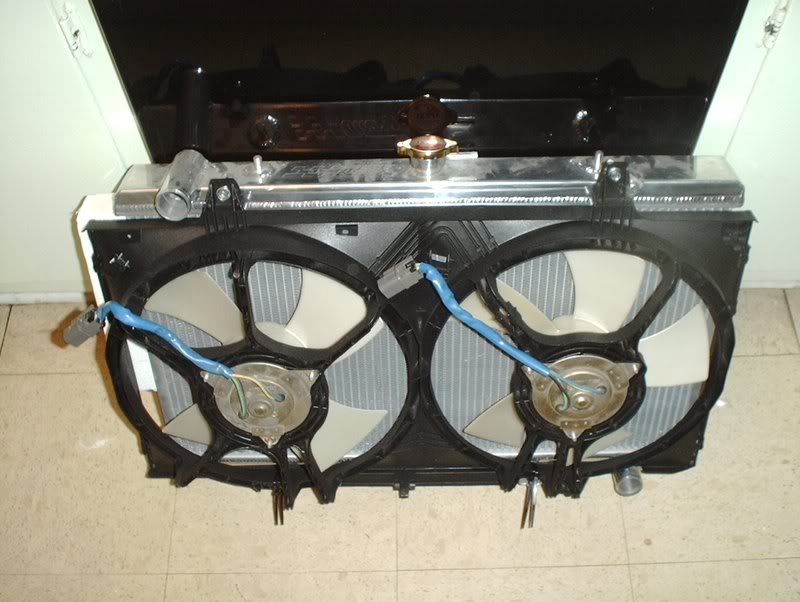
I decided to get a dual fan controller for the set of Altima fans that I have.
Tools needed:
Wire strippers
Extra wire(which I don't have at the moment)
While researching the wiring of the Altima fans, I read many threads looked at many pics and diagrams and I think that I have the initial setup for wiring these fans in my head but I'm still not sure about how to wire them for power. Should I wire them up for low power or high power? I read that wiring them on high power will burn out the fans prematurely or lessen the fan motors life. From my understanding that was if the fans were wired directly to the battery, someone correct me if I'm wrong but my question is this...will it matter if I run them through a fan controller? I'm assuming this because the fan controller is drawing it's power straight from the battery and the fans will be getting their power from the fan controller correct???
Here's some of the info that I came across.
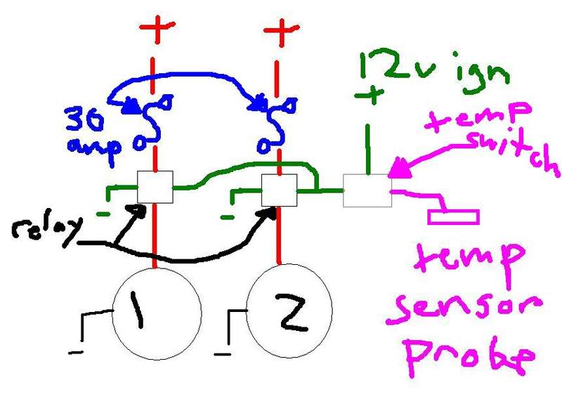
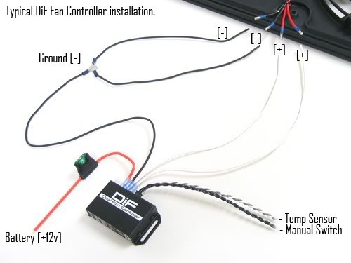
This is the diagram that I decided to use along with the following...
I(Someone else) pulled this from Zilvia.net
+12v blue, (-12v black & -12v green) == low speed
+12v yellow, (-12v black & -12v green) == high speed
(+12v blue & +12v yellow), (-12v black & -12v green) == fans don't spin at all!
--------------------------------------------------------------------------------
Low Speed: blue connects to +12v source, black and green connect to ground.
High speed: yellow connects to +12v source, black and green connect to ground.
--------------------------------------------------------------------------------
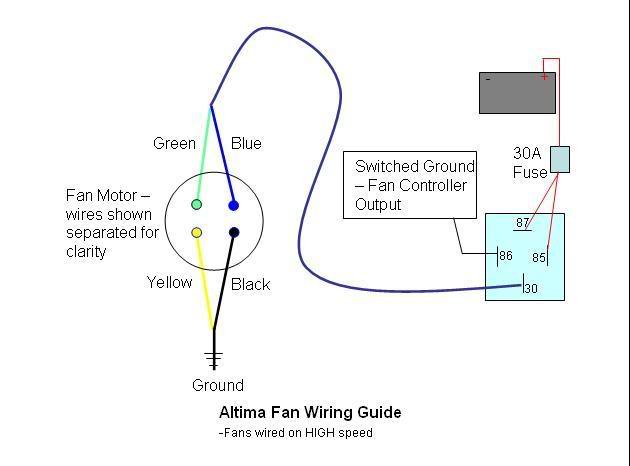
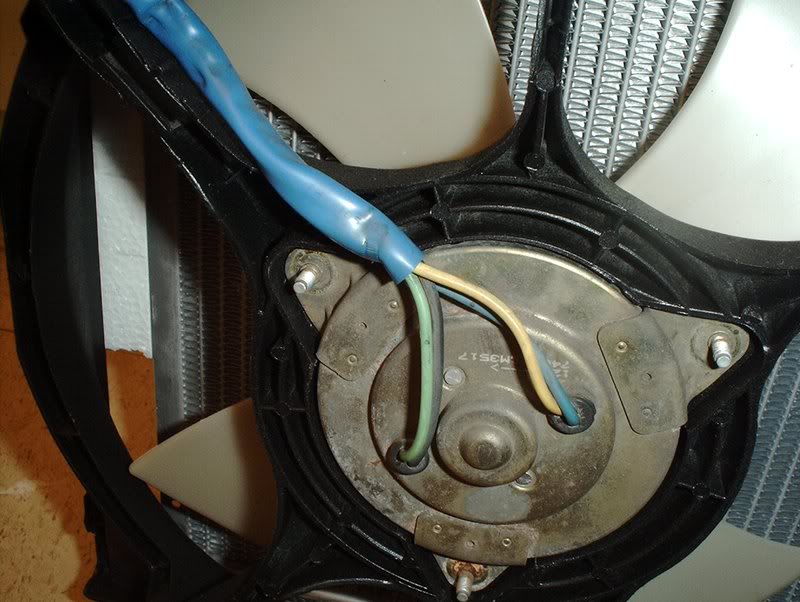
These elec fans have 4 wires EACH.
2 go to 12V
2 go to GROUND
Low speed requires ONE 12V lead and ONE ground lead...
High Speed requires BOTH 12V active and BOTH Grounds active.
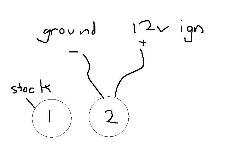
On my 240 and 200sx have the same color's on the fans and the FSM's state the same pattern.
BLUE & GREEN are the two 12V sources
YELLOW & BLACK are the GROUND sources.
BLUE 12V & YELLOW Ground will give LOW speed
BLUE 12V & BLACK Ground will also give LOW speed
GREEN 12V & YELLOW Ground will also give LOW speed
GREEN 12V & BLACK Ground will also give LOW speed
BLUE 12V & GREEN 12V with YELLOW ground & BLACK ground will give HIGH speed....
This is where I'm at on the fan wiring, I think I'm going to wire them for low power unless someone who's done this informs me that with a fan controller it won't matter.
From FRSport...
----------------------------------------------------------------------------------------------
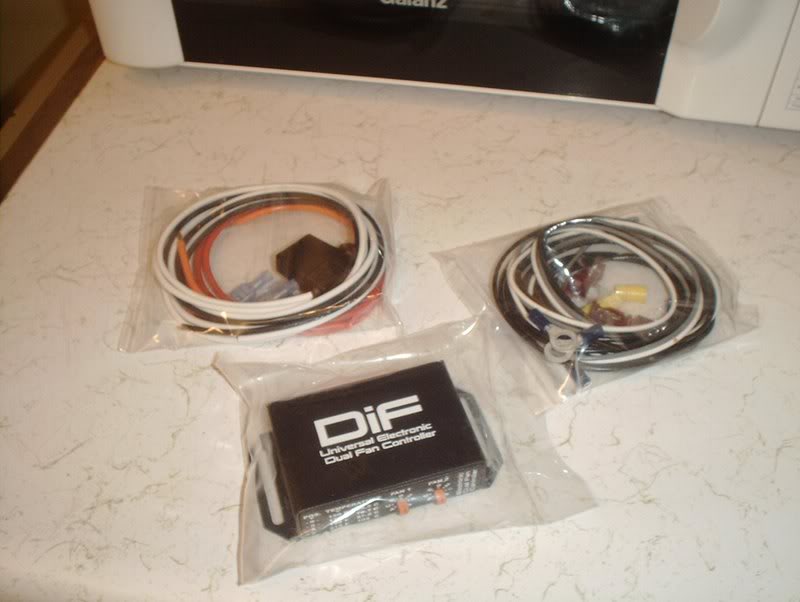
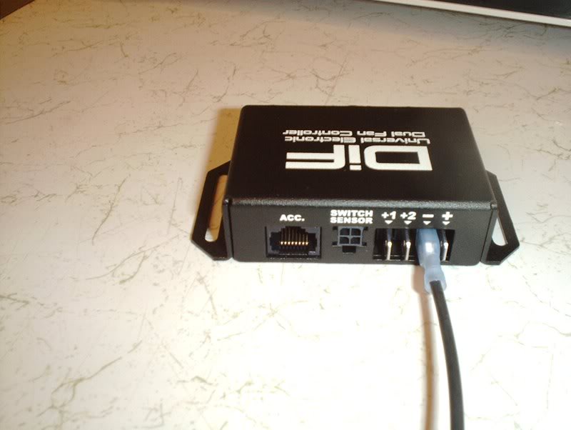
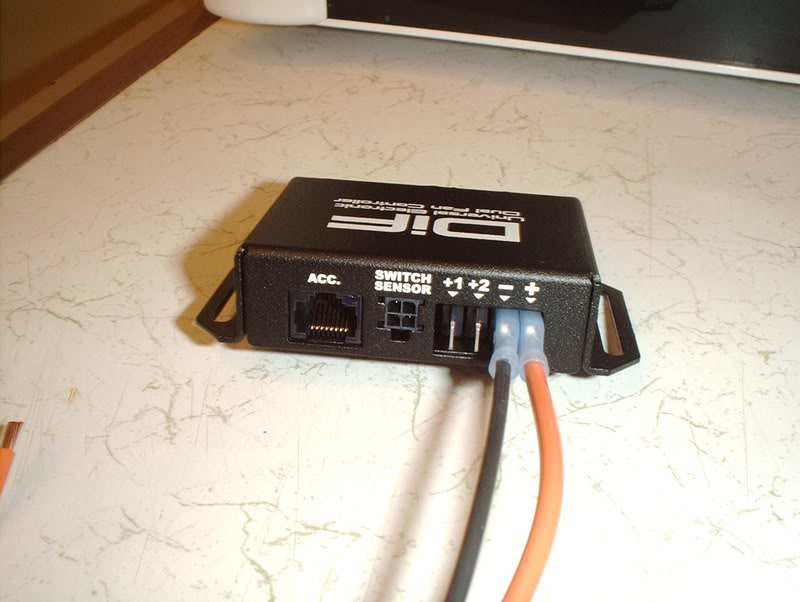
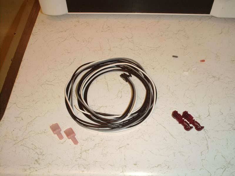
I got a DIF fan controller from Phase2motorsports.
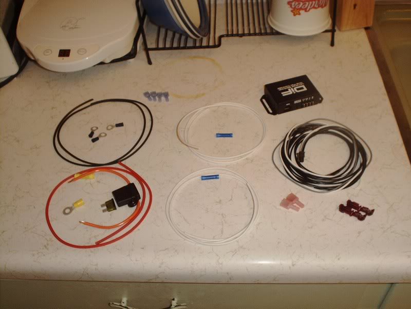
Break it out and make sure that you got every part on the list.
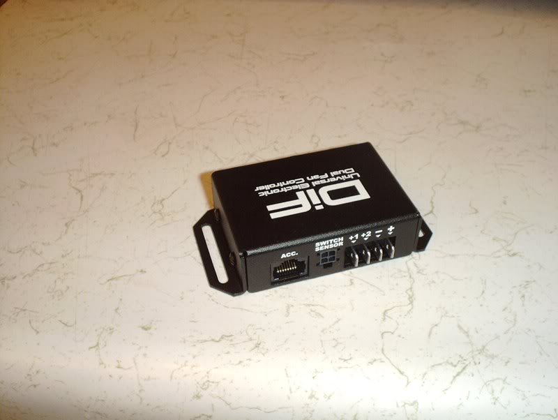
Back
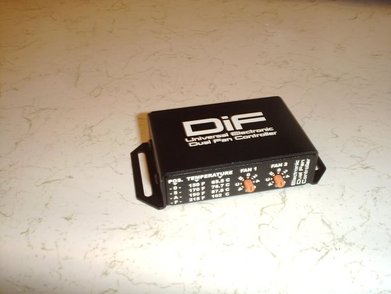
Front
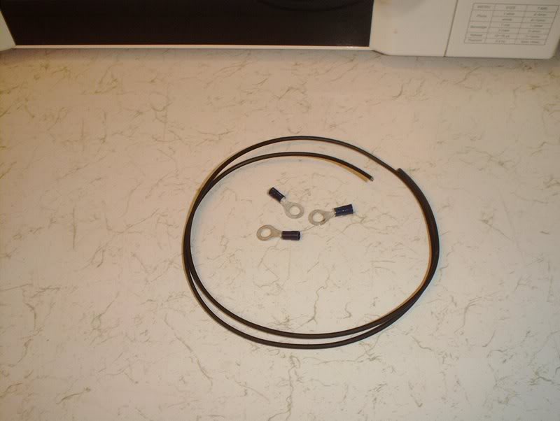
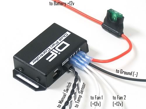
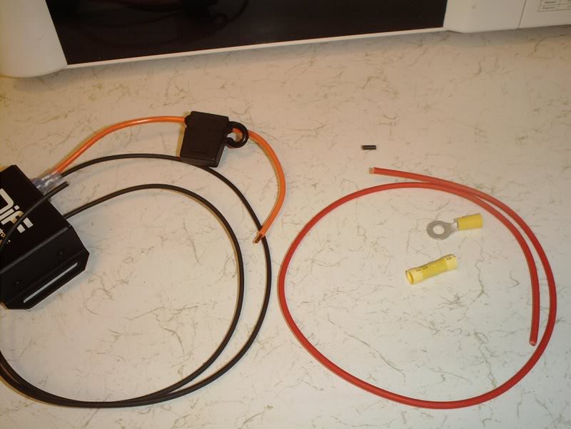
I'm going to start with the fan controller wiring. First up, the ground or BAT- on the back of the fan controller.
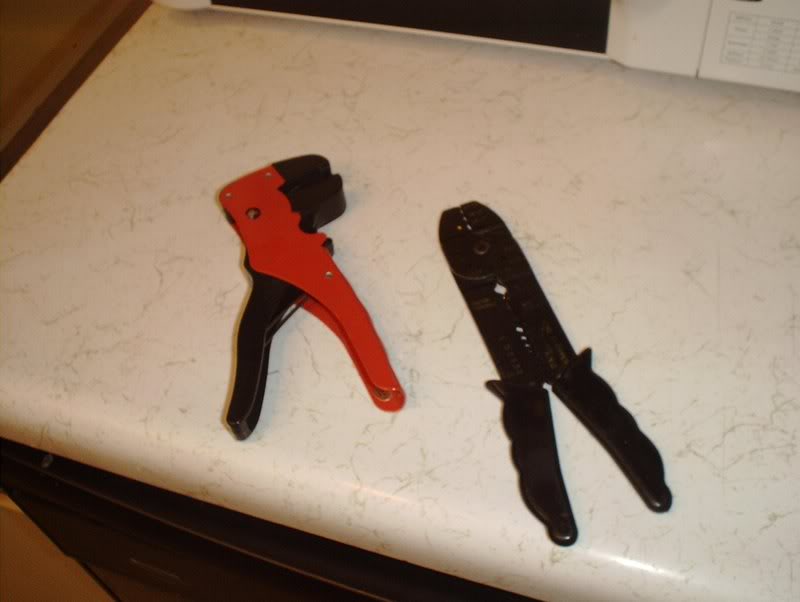
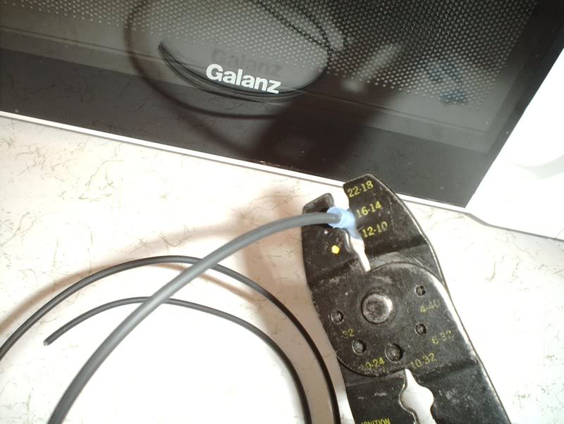
Gonna need a pair of wire strippers for this.
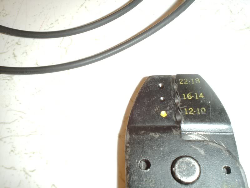
Particularly for the crimp sizing.
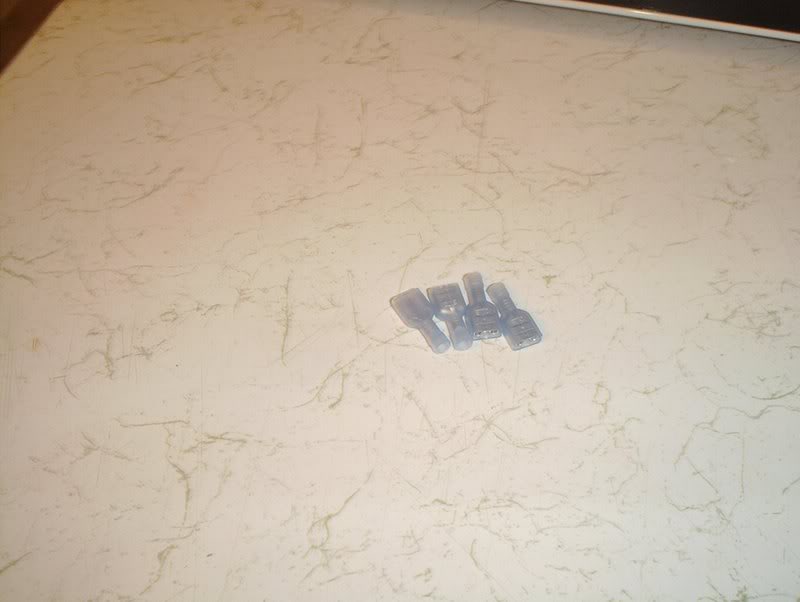
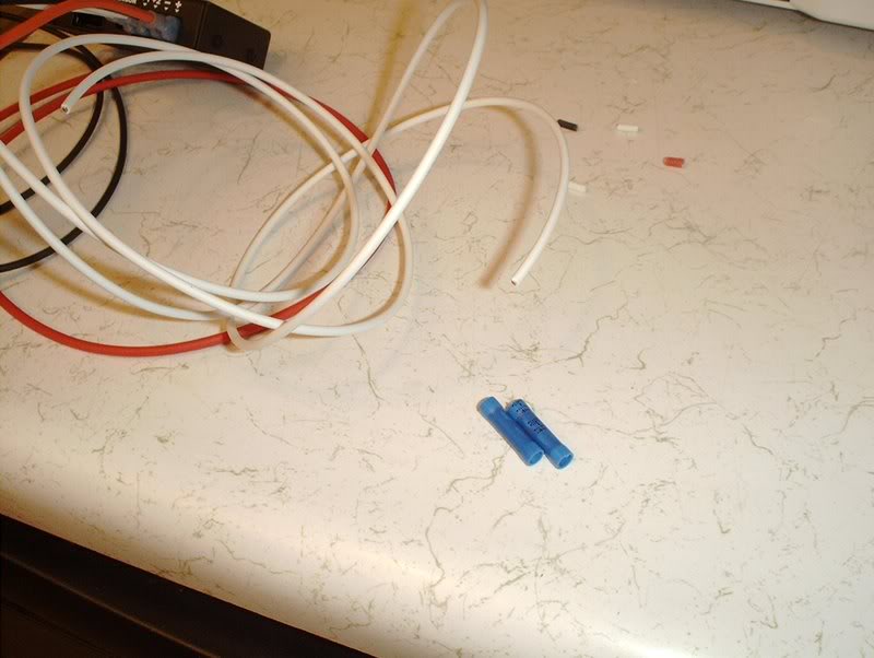
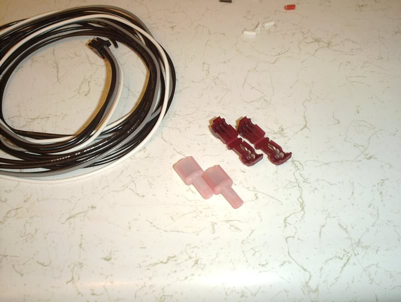
These are the four connectors you will be crimping, they're all 16-14.
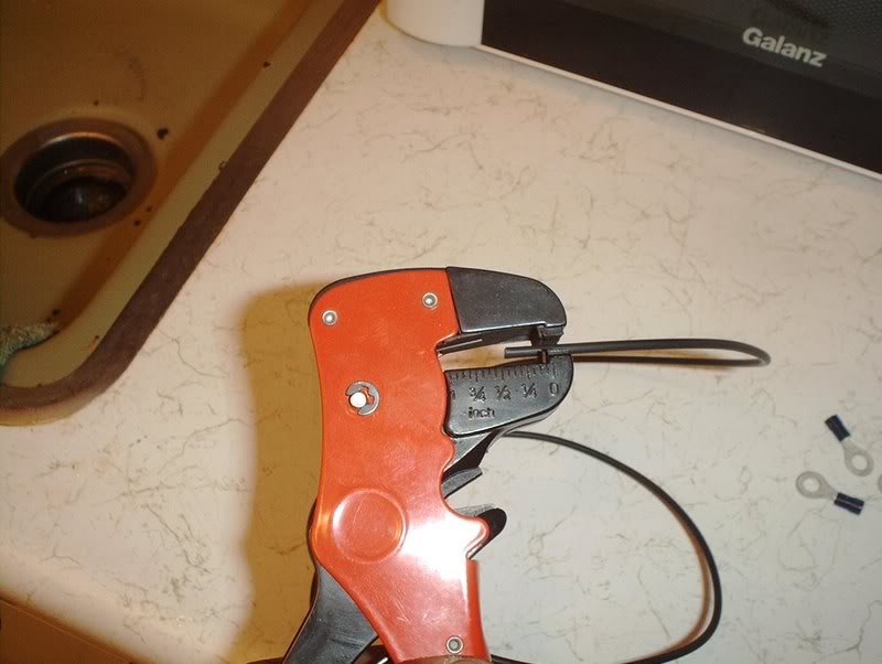
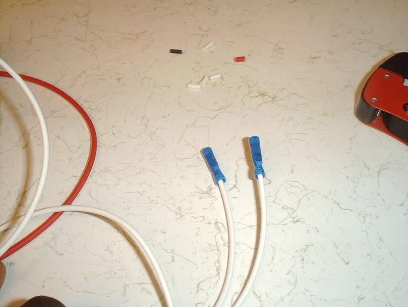
Strip the wire.
Like so.
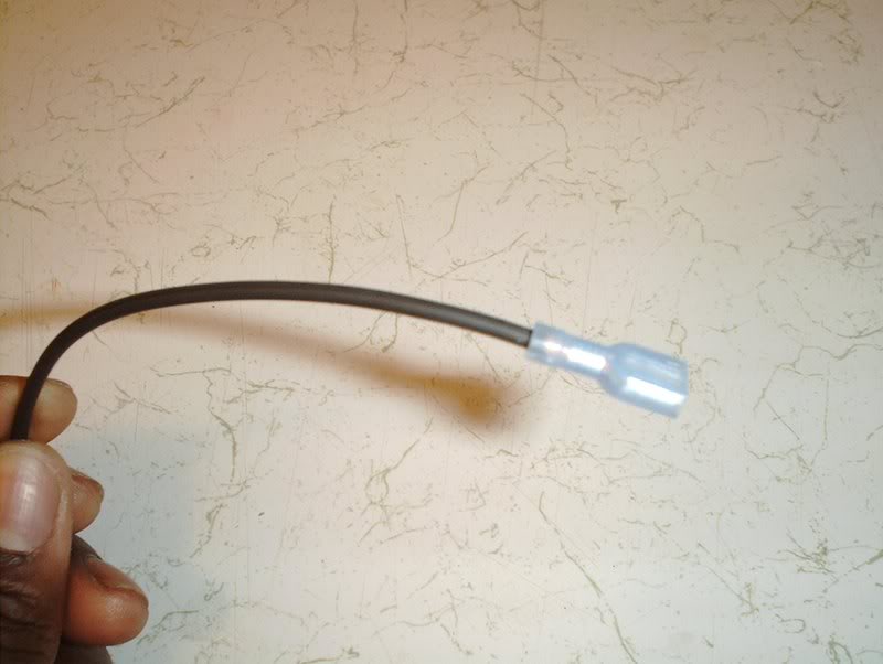
Put the connector on.
Crimp the connector to 16-14.
Ready.
Plug this in to the ground outlet or BAT-. I need some extra wire for the opposite end of the wire that will be the two grounds coming from the fan but the wire that I have lying around is too small so I'll have to wait on that, besides I still haven't figured out exactly if I want to wire the fans for high or low power.
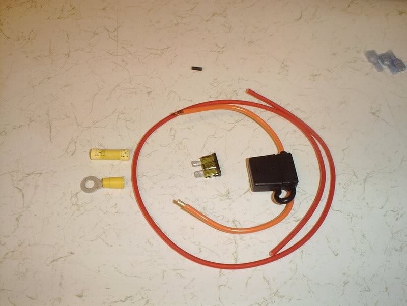
Now for the power or BAT+ for the fan contoller.
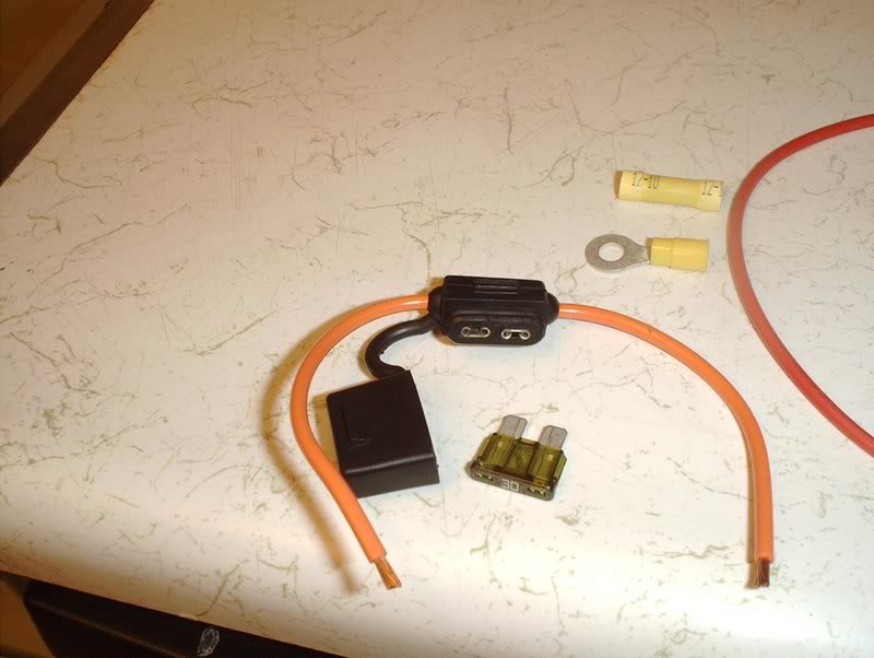
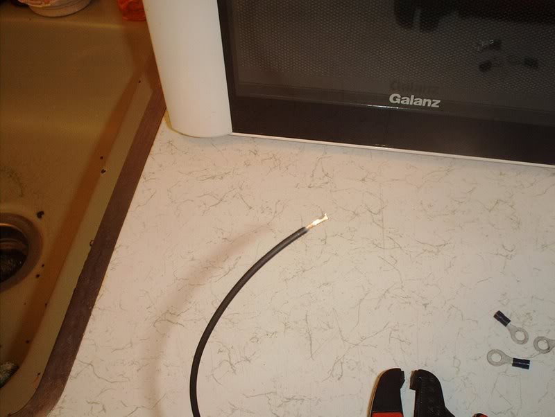
This wire with the fusible link.
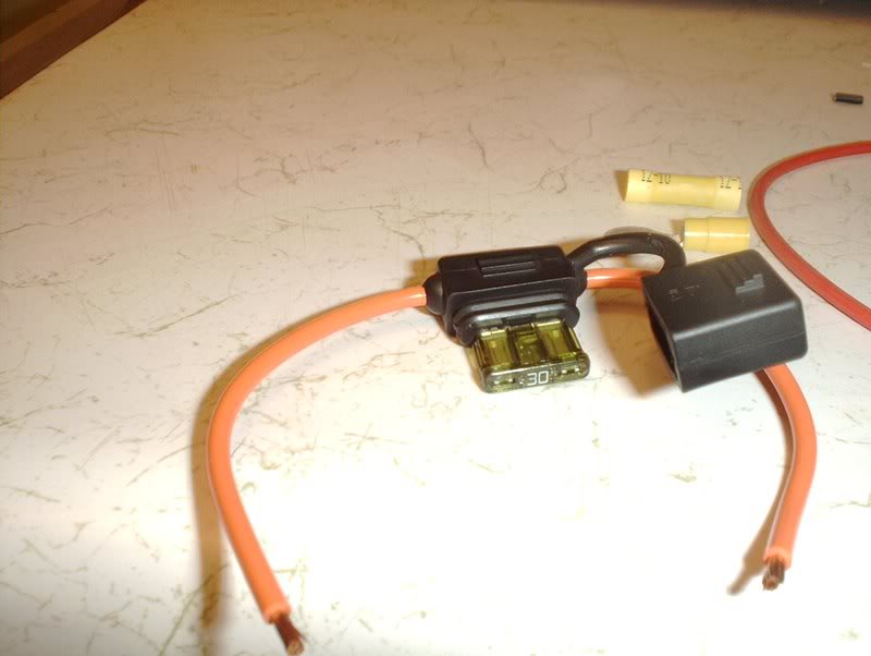
Pop the cover place the fuse...
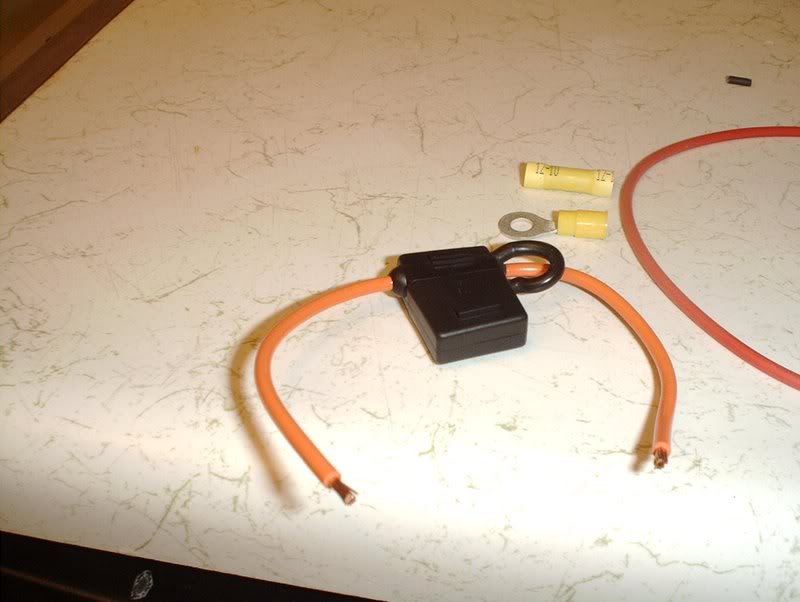
and close it back.
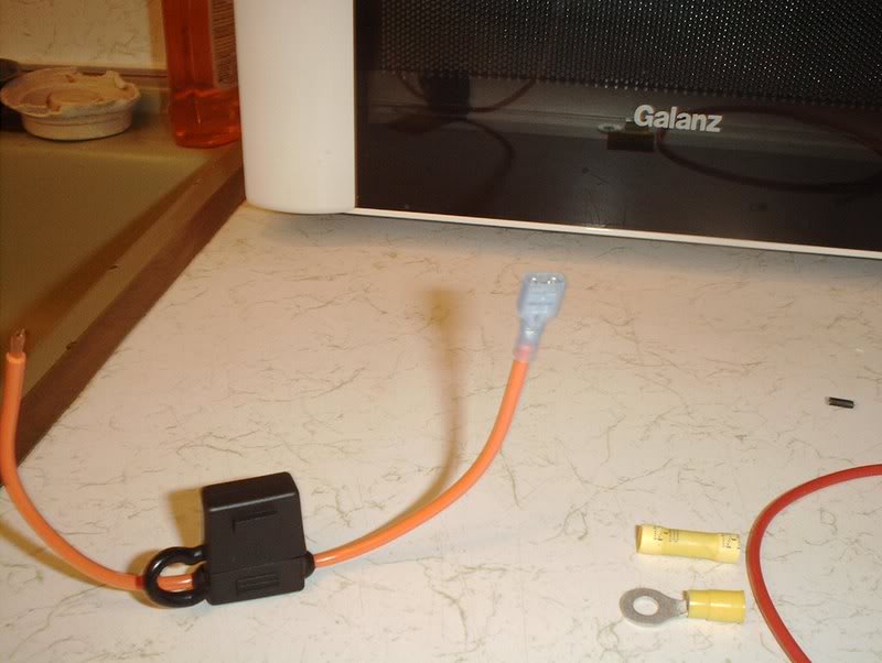
Place a connector on the end and crimp to 16-14, the wire is already stripped.
Plug into the positive outlet or BAT+.
This is the provided extra wire for the other side of this fusible link.
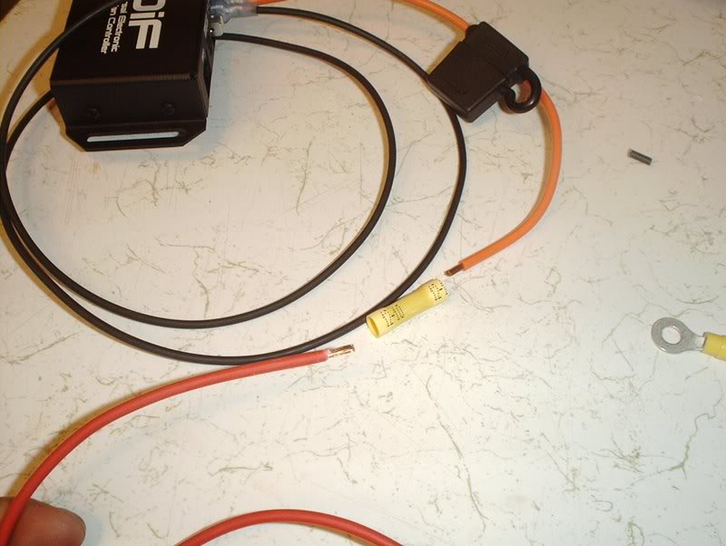
Connect like so.
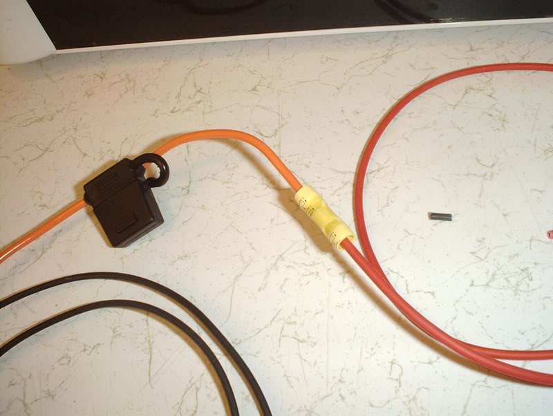
This gets crimped to 12-10.
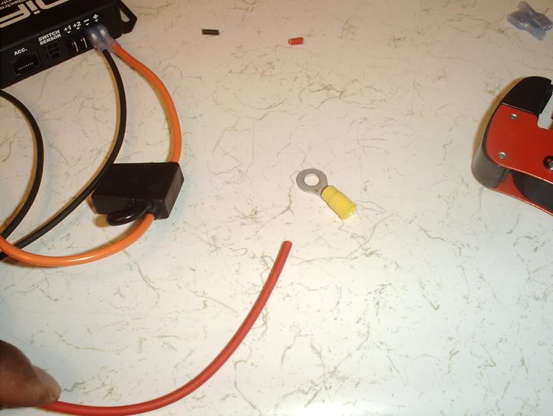
This is the side of the wire that will be connected to the battery for power, I'm not going to strip, crimp and connect here until swap day because the instructions say to keep this wire short and I don't know how much I'll need to shave.
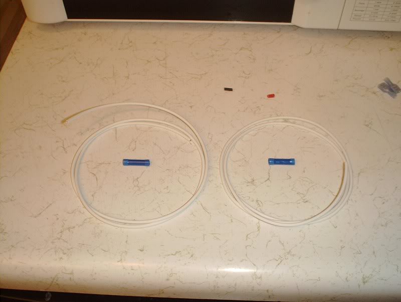
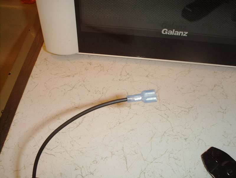
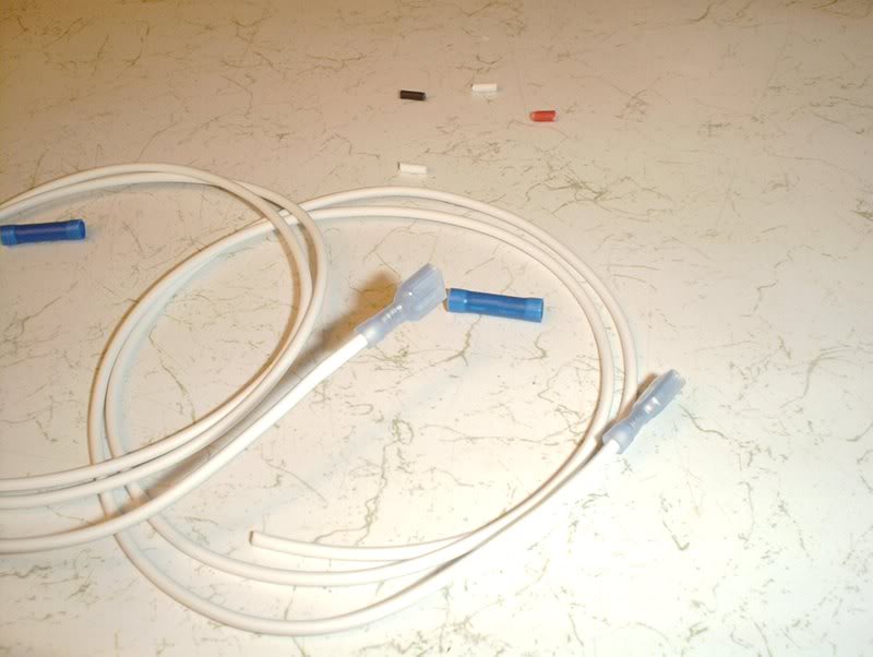
Next I moved to FAN+1 and FAN+2. These white wires will connect to the FAN+1 and FAN+2 on the back of the fan controller.
Strip, connect and crimp to 16-14.
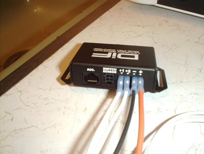
Plug into FAN+1 and FAN+2.
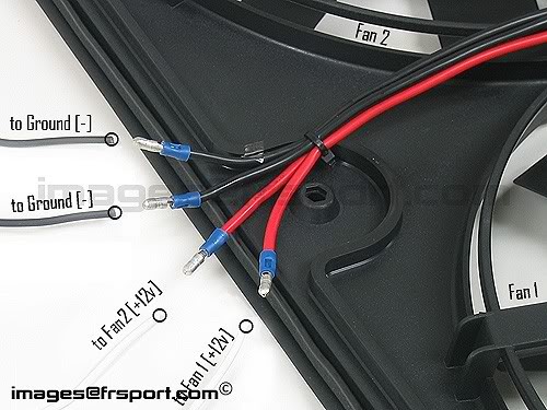
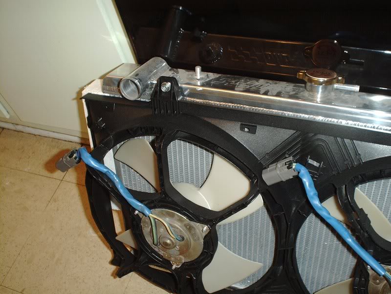
The other ends of these wires will accept the two positive wires from each of the dual fans.
Strip, connect and crimp to 16-14.
Next is the SWITCH SENSOR.
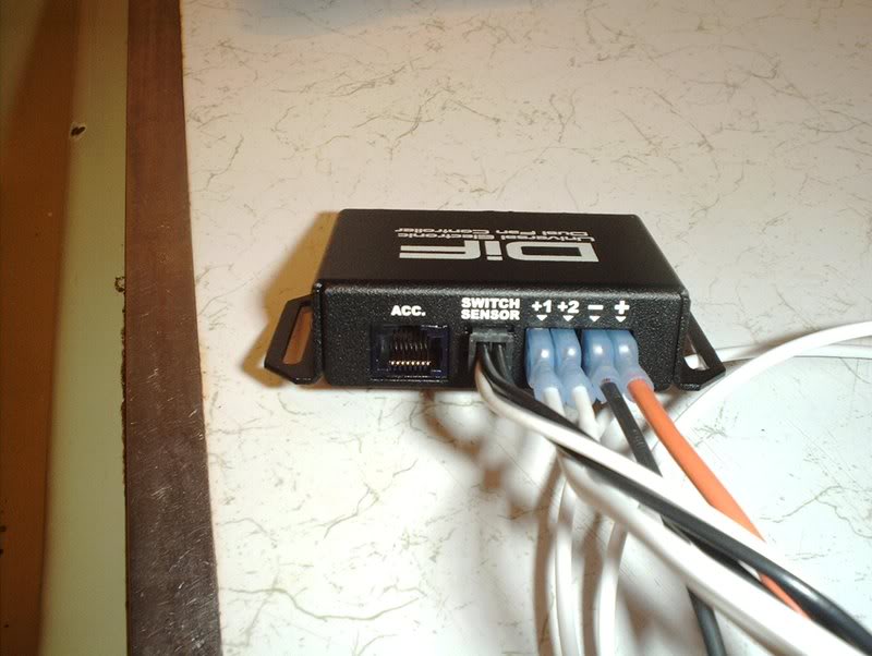
It simply plugs into the SWITCH SENSOR outlet.
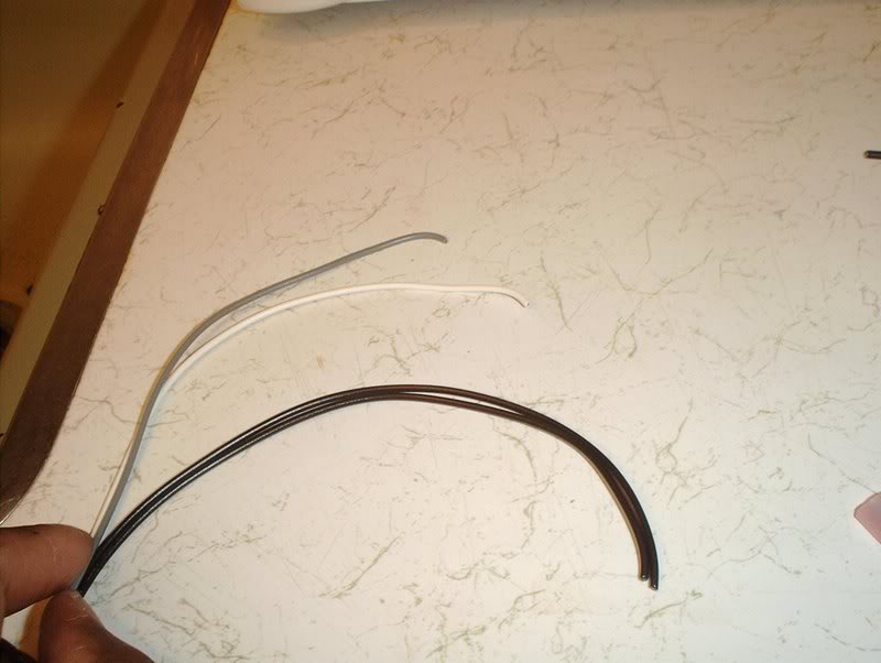
For the other end there are four wires.
WHITE-to coolant temp positive.
GRAY-to coolant temp negative.
BLACK-????
BLACK-????(ground I'm assuming for these two but where?)
I also have no definite idea where these will be connected either.
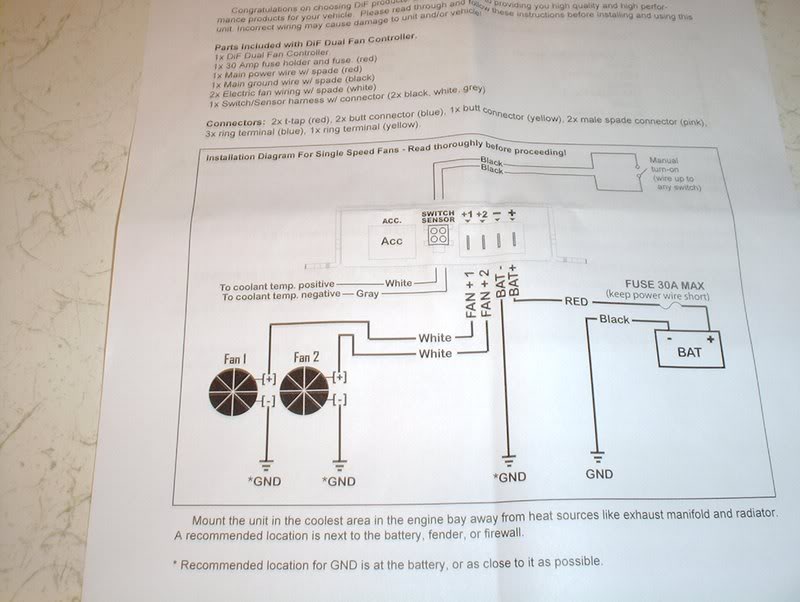
INSTRUCTIONS
I don't have the right wire to do the fan wiring itself and like I said before I haven't totally decided on whether to wire them up for high or low power.
TO BE CONTINUED...
Tools needed:
Wire strippers
Extra wire(which I don't have at the moment)
While researching the wiring of the Altima fans, I read many threads looked at many pics and diagrams and I think that I have the initial setup for wiring these fans in my head but I'm still not sure about how to wire them for power. Should I wire them up for low power or high power? I read that wiring them on high power will burn out the fans prematurely or lessen the fan motors life. From my understanding that was if the fans were wired directly to the battery, someone correct me if I'm wrong but my question is this...will it matter if I run them through a fan controller? I'm assuming this because the fan controller is drawing it's power straight from the battery and the fans will be getting their power from the fan controller correct???
Here's some of the info that I came across.
This is the diagram that I decided to use along with the following...
I(Someone else) pulled this from Zilvia.net
+12v blue, (-12v black & -12v green) == low speed
+12v yellow, (-12v black & -12v green) == high speed
(+12v blue & +12v yellow), (-12v black & -12v green) == fans don't spin at all!
--------------------------------------------------------------------------------
Low Speed: blue connects to +12v source, black and green connect to ground.
High speed: yellow connects to +12v source, black and green connect to ground.
--------------------------------------------------------------------------------
These elec fans have 4 wires EACH.
2 go to 12V
2 go to GROUND
Low speed requires ONE 12V lead and ONE ground lead...
High Speed requires BOTH 12V active and BOTH Grounds active.
On my 240 and 200sx have the same color's on the fans and the FSM's state the same pattern.
BLUE & GREEN are the two 12V sources
YELLOW & BLACK are the GROUND sources.
BLUE 12V & YELLOW Ground will give LOW speed
BLUE 12V & BLACK Ground will also give LOW speed
GREEN 12V & YELLOW Ground will also give LOW speed
GREEN 12V & BLACK Ground will also give LOW speed
BLUE 12V & GREEN 12V with YELLOW ground & BLACK ground will give HIGH speed....
This is where I'm at on the fan wiring, I think I'm going to wire them for low power unless someone who's done this informs me that with a fan controller it won't matter.
From FRSport...
----------------------------------------------------------------------------------------------
I got a DIF fan controller from Phase2motorsports.
Break it out and make sure that you got every part on the list.
Back
Front
I'm going to start with the fan controller wiring. First up, the ground or BAT- on the back of the fan controller.
Gonna need a pair of wire strippers for this.
Particularly for the crimp sizing.
These are the four connectors you will be crimping, they're all 16-14.
Strip the wire.
Like so.
Put the connector on.
Crimp the connector to 16-14.
Ready.
Plug this in to the ground outlet or BAT-. I need some extra wire for the opposite end of the wire that will be the two grounds coming from the fan but the wire that I have lying around is too small so I'll have to wait on that, besides I still haven't figured out exactly if I want to wire the fans for high or low power.
Now for the power or BAT+ for the fan contoller.
This wire with the fusible link.
Pop the cover place the fuse...
and close it back.
Place a connector on the end and crimp to 16-14, the wire is already stripped.
Plug into the positive outlet or BAT+.
This is the provided extra wire for the other side of this fusible link.
Connect like so.
This gets crimped to 12-10.
This is the side of the wire that will be connected to the battery for power, I'm not going to strip, crimp and connect here until swap day because the instructions say to keep this wire short and I don't know how much I'll need to shave.
Next I moved to FAN+1 and FAN+2. These white wires will connect to the FAN+1 and FAN+2 on the back of the fan controller.
Strip, connect and crimp to 16-14.
Plug into FAN+1 and FAN+2.
The other ends of these wires will accept the two positive wires from each of the dual fans.
Strip, connect and crimp to 16-14.
Next is the SWITCH SENSOR.
It simply plugs into the SWITCH SENSOR outlet.
For the other end there are four wires.
WHITE-to coolant temp positive.
GRAY-to coolant temp negative.
BLACK-????
BLACK-????(ground I'm assuming for these two but where?)
I also have no definite idea where these will be connected either.
INSTRUCTIONS
I don't have the right wire to do the fan wiring itself and like I said before I haven't totally decided on whether to wire them up for high or low power.
TO BE CONTINUED...
08-19-2008, 02:23 PM
#194
Contributing Member
Thread Starter
Join Date: Sep 2002
Location: Starkville, MS.
Posts: 1,192
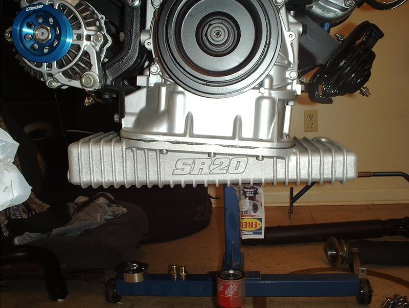
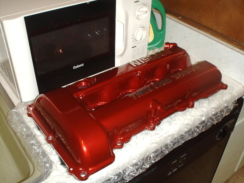
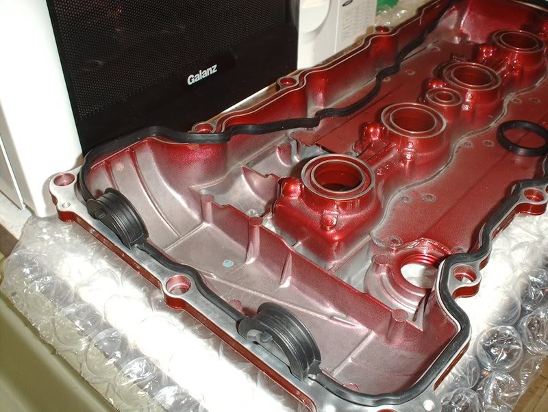
Valve Cover
I got my stuff back from Bonehead Performance that I sent off to be powdercoated and I have to say that they did an excellent job.
I sent them a new unpainted valve cover that I had powdercoated in anodized red...
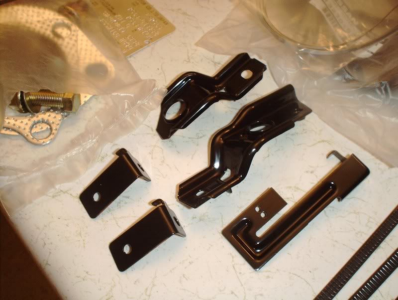
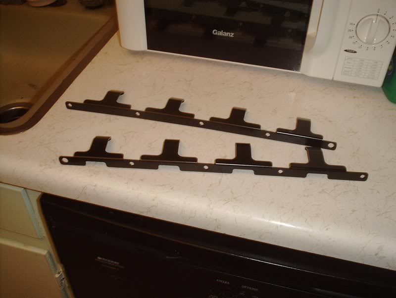
and I sent some harness and radiator brackets.
I got some new hardware for the valvecover.
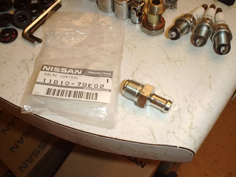
Valve control part#: 11810-79E02
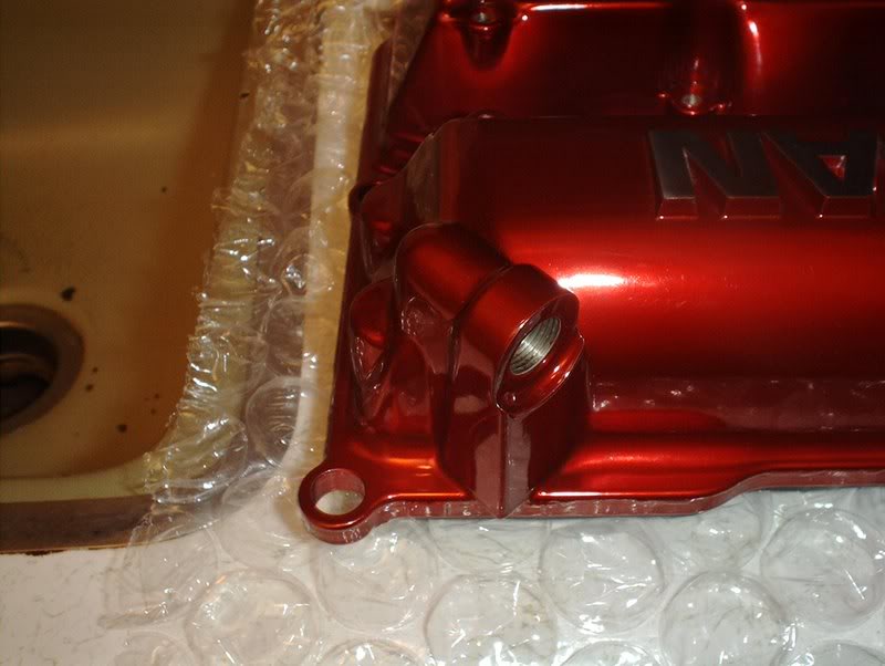
The valve control goes here. It receives the hose from the fuel rail.
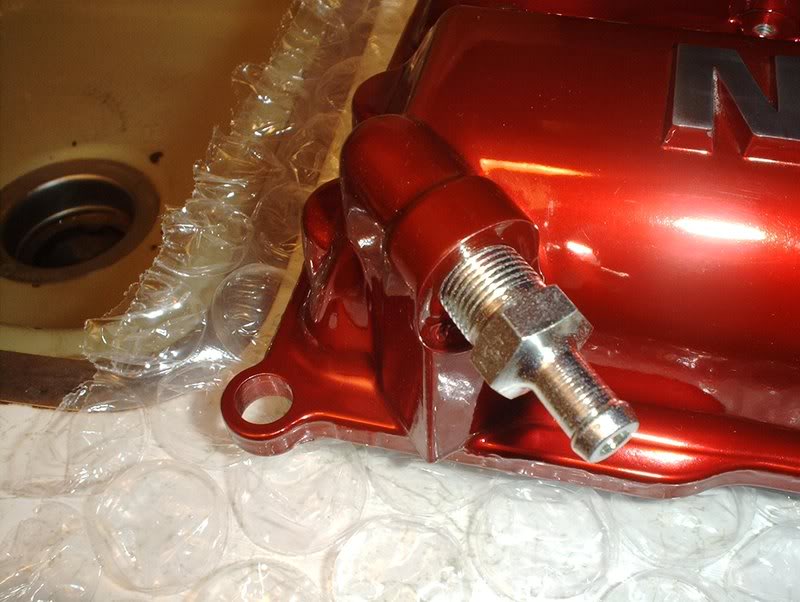
Just place it.
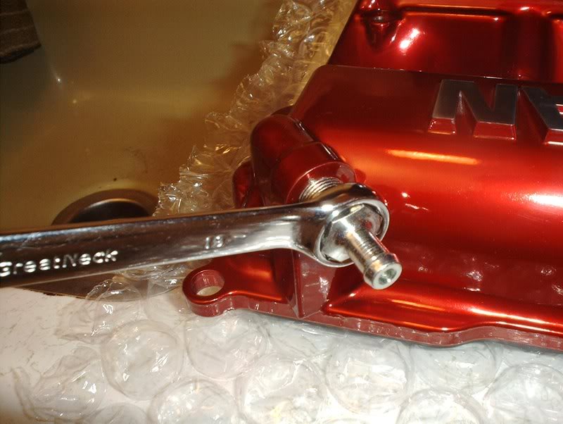
I messed up my deepwell 19mm socket so I just used a 19mm wrench.
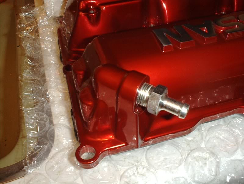
There are no torque specs for this in the FSM. The old valve control was turned in with just 4 threads showing so I did the same with this one.
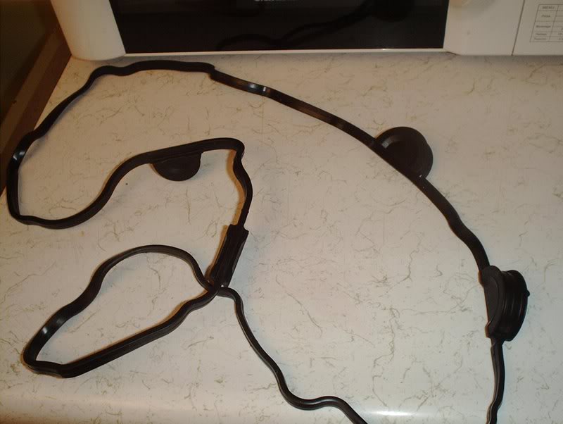
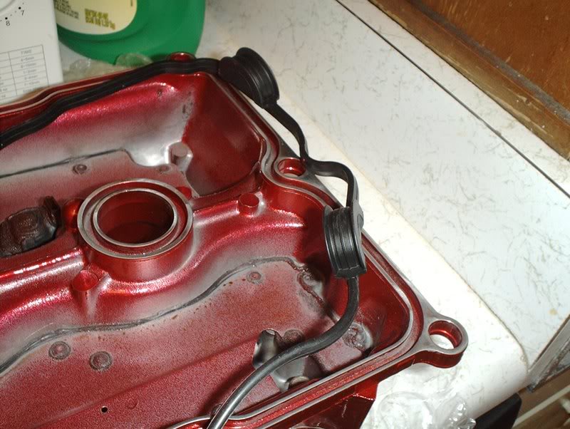
Valve cover gasket part#: 13270-52F00
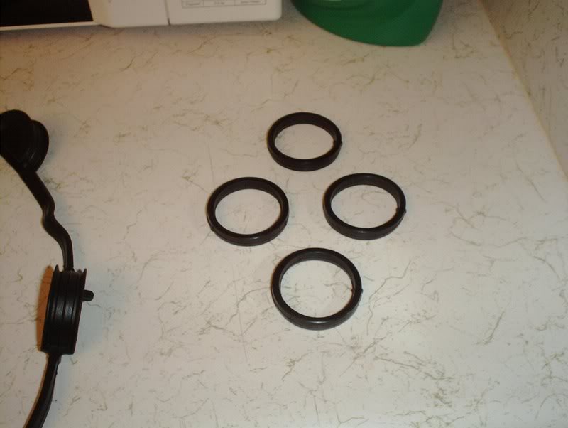
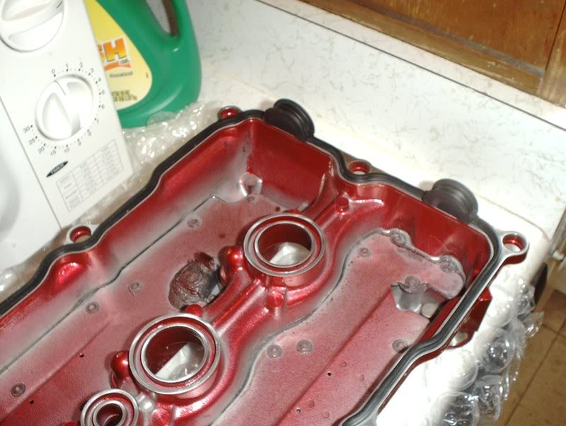
Spark plug gasket part#: 13271-52F00
I realized that I did not have this gasket, I emailed a couple of places but haven't gotten any responses so can anyone tell me where I can get this gasket or should I re-use the old one if it's not in bad shape...something that I don't want to do.
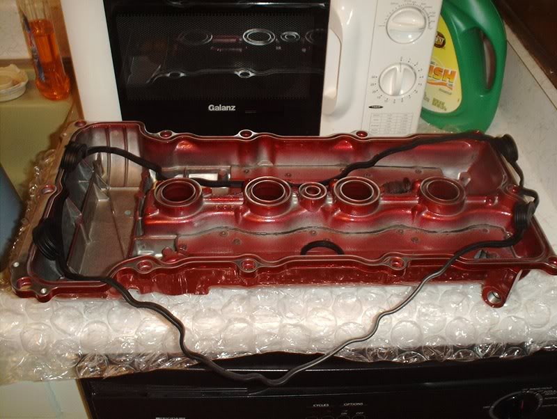
I placed the valve cover gasket on and worked it into place.
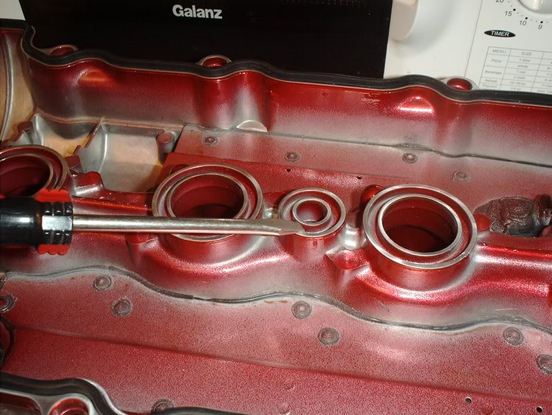
From what I learned...
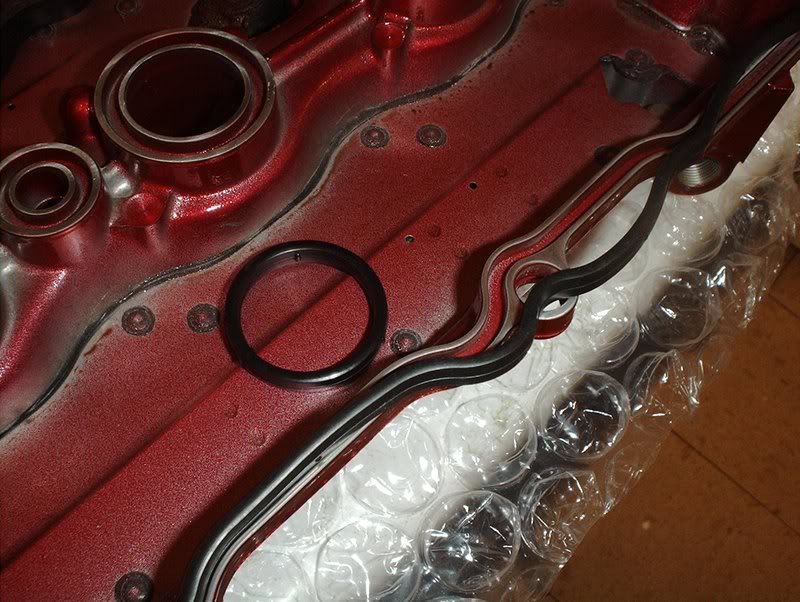
I'll just need to put liquid gasket on the four half moon sections on the front and back of the block.
I cleaned up the oil around the edges on the block and removed old traces of liquid gasket.
Question, what type of gasket should I use for the spark plug gaskets? I'm sitting on a tube of Ultra-black and the orange/red RTV and I've read about people using the Ultra-gray. Which one should I go with?
I sent them a new unpainted valve cover that I had powdercoated in anodized red...
and I sent some harness and radiator brackets.
I got some new hardware for the valvecover.
Valve control part#: 11810-79E02
The valve control goes here. It receives the hose from the fuel rail.
Just place it.
I messed up my deepwell 19mm socket so I just used a 19mm wrench.
There are no torque specs for this in the FSM. The old valve control was turned in with just 4 threads showing so I did the same with this one.
Valve cover gasket part#: 13270-52F00
Spark plug gasket part#: 13271-52F00
I realized that I did not have this gasket, I emailed a couple of places but haven't gotten any responses so can anyone tell me where I can get this gasket or should I re-use the old one if it's not in bad shape...something that I don't want to do.
I placed the valve cover gasket on and worked it into place.
From what I learned...
I'll just need to put liquid gasket on the four half moon sections on the front and back of the block.
I cleaned up the oil around the edges on the block and removed old traces of liquid gasket.
Question, what type of gasket should I use for the spark plug gaskets? I'm sitting on a tube of Ultra-black and the orange/red RTV and I've read about people using the Ultra-gray. Which one should I go with?
08-19-2008, 02:46 PM
#195
Contributing Member
Thread Starter
Join Date: Sep 2002
Location: Starkville, MS.
Posts: 1,192
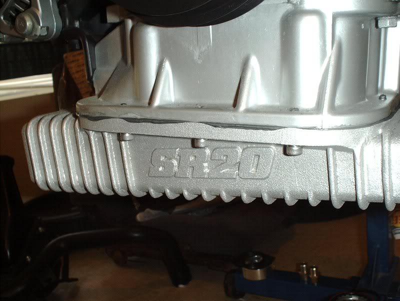
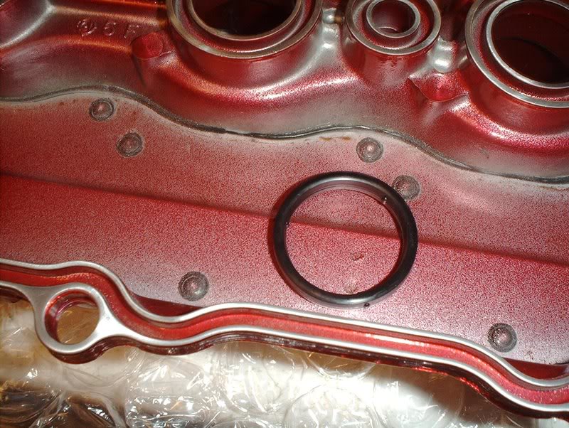
Rocker Arm Stopper Install
Little problem with this! I've got a question for those that have installed RAS on a S13 SR20DET. I installed mine to specifications but now my valve cover will not sit flush with the block like it did before. Now I know that the S14/S15 valve covers need to be modified, something has to be cut underneath for them to fit properly over the RAS but everyone says that this is not necessary with the S13 valve covers. Am I just thinking too much about this, will the tightening of the valve cover washers take care of this problem? I've actually been trying out some things on the old valve cover, I was hoping to have this figured out by the time I got my new valve cover back but so far no go. I did get it to sit quite a bit more flush to the block but there is still some space. It appears to be making contact where it would on the S14/S15 valve covers on the intake cams rear oil tube at the top, I trimmed this section. The next place it appears to be making contact is on the exhaust RAS, the sides are rubbing the valve cover where the two indentions are on the exhaust side near where the screws go. WTF!!!