
All About Tps

Thread Starter
Registered User
Joined: Sep 2005
Posts: 292
From: NC
All About Tps
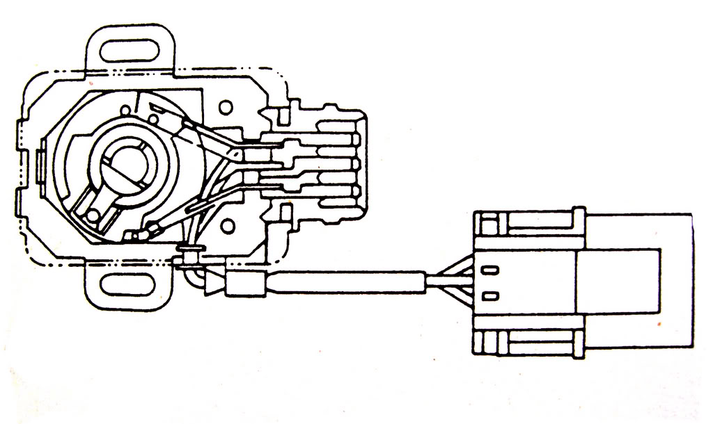
The TP sensor is a potentiometer. It is mounted on the side of the TB and is connected to the throttle plate shaft. The sensor monitors throttle plate movement and position, and transmits an appropriate electrical signal to the ECU. These signals are used by the ECU to adjust air/fuel mixture and timing according to engine load. The TP sensor is adjustable on the 240sx. Automatic transmission TP sensors contain position switches. These switches provide a signal to the ECU when the engine is at idle and WOT.
TPS sensors for the 240sx differ by OBDI or OBDII and by auto and manual. I hope this information helps anyone confused by TPS sensors.
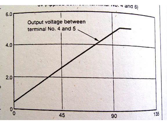
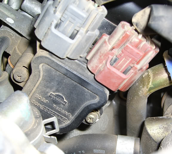
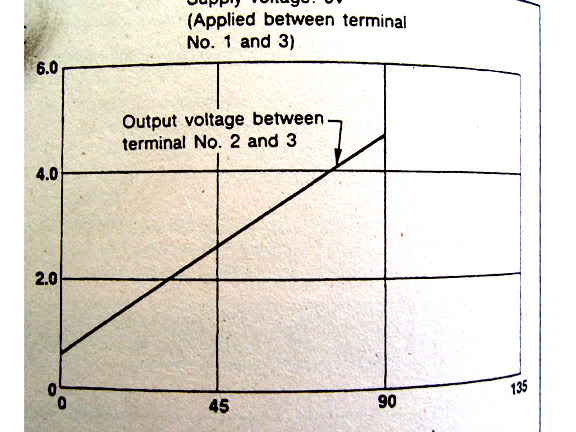
As seen below, the Auto and Manual have different output voltages, look different, and have different parts numbers:
MANUAL (OBDII SHOWN) A22 658 N02:

AUTO (OBDII SHOWN) A22 658 E02:
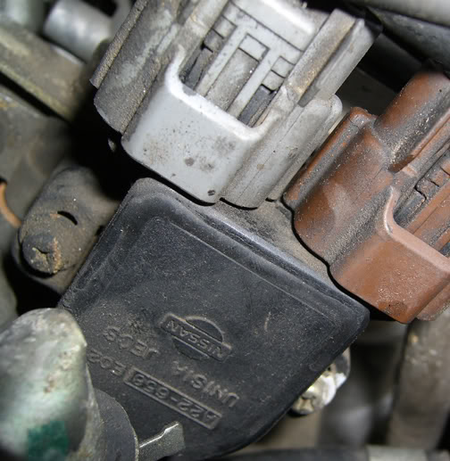
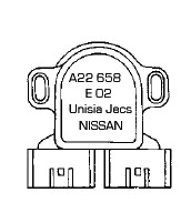
Notice that OBDII (auto or manual) have 6 prongs attached directly to the sensor. OBDI have 3 prongs dangling from a pigtail.
OBDI
TESTING THE TPS
1. Disconnect the electircal harness from the sensor
2. Check resistance etween the connector terminals
3. resistance for 1996-1998 models should be as follows
throttle closed: .6 Kohm
throttle partially open: .5 - 4 kohm
throttle fully open: 5 kohm
4. resistance for 1995 models should be as follows
throttle closed: 1 Kohm
throttle partially open: 1-10 kohm
throttle fully open: 10 kohm
5. resistance for 1993-1994 models should be as follows
throttle closed: 2 Kohm
throttle partially open: 2-10 kohm
throttle fully open: 10 kohm
6. Slowly rotate the throttle shaft and monitor the ohmmeter for a continuous steady change in resistance. Any sudden jumps or irregularities in resistance indicate a bad sensor
7. if resistane is not within spec, sensor may be faulty
8. if resistance is within spec check the circuits back to the ECU
9. connect the harness to the sensor
POSITION SWITCHES (auto):
1. disconnect the electrical harness from the sensor
2. check continuity between the connector terminals
3. when throttle is placed in the appropriate position (idle or WOT) continuity should exist
4. when throttle is not in the idle or WOT position, continuity should NOT exist
5. if continuity is not specified, the sensor is faulty and the whole TPS must be replaced
Consult the FSM or Chilton for diagrams on which terminals to measure continuity/resistance across.
TPS sensors for the 240sx differ by OBDI or OBDII and by auto and manual. I hope this information helps anyone confused by TPS sensors.
As seen below, the Auto and Manual have different output voltages, look different, and have different parts numbers:
MANUAL (OBDII SHOWN) A22 658 N02:
AUTO (OBDII SHOWN) A22 658 E02:
Notice that OBDII (auto or manual) have 6 prongs attached directly to the sensor. OBDI have 3 prongs dangling from a pigtail.
OBDI
TESTING THE TPS
1. Disconnect the electircal harness from the sensor
2. Check resistance etween the connector terminals
3. resistance for 1996-1998 models should be as follows
throttle closed: .6 Kohm
throttle partially open: .5 - 4 kohm
throttle fully open: 5 kohm
4. resistance for 1995 models should be as follows
throttle closed: 1 Kohm
throttle partially open: 1-10 kohm
throttle fully open: 10 kohm
5. resistance for 1993-1994 models should be as follows
throttle closed: 2 Kohm
throttle partially open: 2-10 kohm
throttle fully open: 10 kohm
6. Slowly rotate the throttle shaft and monitor the ohmmeter for a continuous steady change in resistance. Any sudden jumps or irregularities in resistance indicate a bad sensor
7. if resistane is not within spec, sensor may be faulty
8. if resistance is within spec check the circuits back to the ECU
9. connect the harness to the sensor
POSITION SWITCHES (auto):
1. disconnect the electrical harness from the sensor
2. check continuity between the connector terminals
3. when throttle is placed in the appropriate position (idle or WOT) continuity should exist
4. when throttle is not in the idle or WOT position, continuity should NOT exist
5. if continuity is not specified, the sensor is faulty and the whole TPS must be replaced
Consult the FSM or Chilton for diagrams on which terminals to measure continuity/resistance across.

Thread
Thread Starter
Forum
Replies
Last Post