Operation Delete 240 insert 180!


 12-13-2006, 08:08 PM
#47
Contributing Member

Join Date: Sep 2006
Location: WI
Posts: 589
yes, the CA is basically a 4 cylinder RB, both have the same style of iron block, compared to the KA and the SR, which both have aluminum blocks.
EDIT: not sure on the validity, but it makes sence. i just read that the CA was made first, and the design for the RB was taken pretty much directly from the CA. *woot baby skyline woot*
EDIT: not sure on the validity, but it makes sence. i just read that the CA was made first, and the design for the RB was taken pretty much directly from the CA. *woot baby skyline woot*
Last edited by cronux; 12-13-2006 at 08:12 PM.
12-14-2006, 06:06 AM
#49
Registered User

Join Date: Jun 2003
Location: Harrisburg, PA
Posts: 8,440
Originally posted by cronux
yes, the CA is basically a 4 cylinder RB, both have the same style of iron block, compared to the KA and the SR, which both have aluminum blocks.
EDIT: not sure on the validity, but it makes sence. i just read that the CA was made first, and the design for the RB was taken pretty much directly from the CA. *woot baby skyline woot*
12-14-2006, 06:17 AM
#50
Registered User
Thread Starter
Join Date: Feb 2005
Location: Binghamton, NY
Posts: 232
Originally posted by 93coupe
another question for trevor on my motor i was missing three vacuum lines right in between the middle of the third intake plenum and the fourth i was wondering where they go??
another question for trevor on my motor i was missing three vacuum lines right in between the middle of the third intake plenum and the fourth i was wondering where they go??
12-14-2006, 06:55 AM
#51
Registered User
Thread Starter
Join Date: Feb 2005
Location: Binghamton, NY
Posts: 232
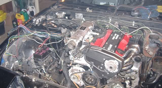
Oh k, back on track with my progress.
Last night my friend and I were able to install the motor and tranny in the usual fashion. The engine and tranny bolted up as if it was built for the chassis using the KA mounts.
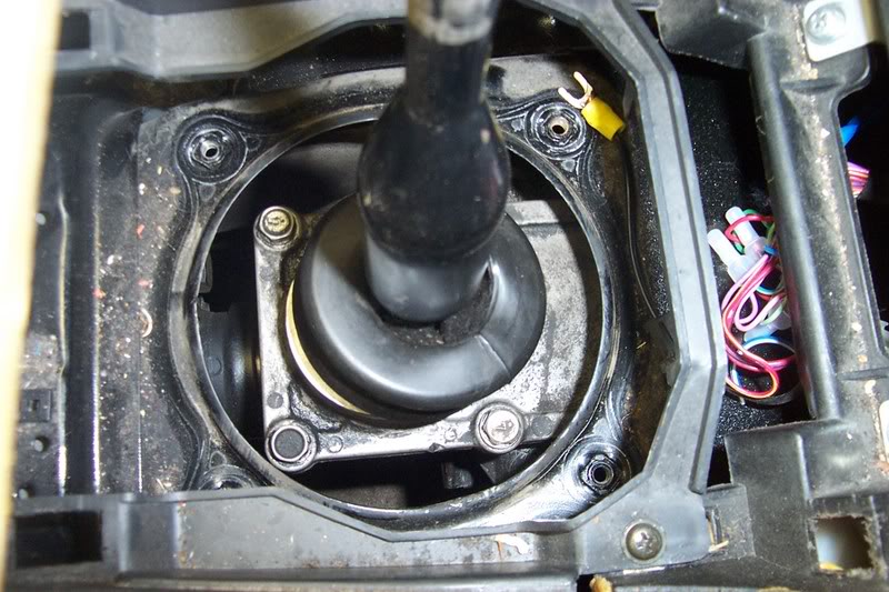
The shifter sat right where it needed to be... but... there was a problem. I'm not sure how big of an issue it is going to be.
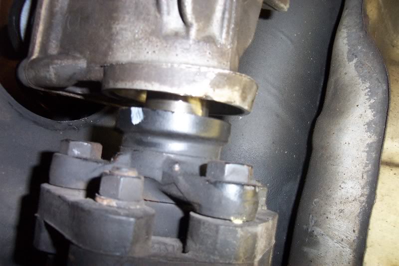
As you can see from the picture, the 1st propeller shaft doesn't mate up completely with the transmission (its about 1/4" short). Prior to installing the the motor/tranny we removed the 1st propeller shaft at the companion flange, and installed it the same way.
So this part of the swap is at a stand still. I am unsure whether there is a simple solution to adjusting the shaft to mate up, or if there is a thicker companion flange to to use, or the need for a longer drive shaft. If anyone knows a solution for this let me know. I'll do some research and see what I can find out myself.
Later this week, I will start the wiring, and connecting hardware. Then, move on to plumbing... I'll keep you all updated.
Last night my friend and I were able to install the motor and tranny in the usual fashion. The engine and tranny bolted up as if it was built for the chassis using the KA mounts.
The shifter sat right where it needed to be... but... there was a problem. I'm not sure how big of an issue it is going to be.
As you can see from the picture, the 1st propeller shaft doesn't mate up completely with the transmission (its about 1/4" short). Prior to installing the the motor/tranny we removed the 1st propeller shaft at the companion flange, and installed it the same way.
So this part of the swap is at a stand still. I am unsure whether there is a simple solution to adjusting the shaft to mate up, or if there is a thicker companion flange to to use, or the need for a longer drive shaft. If anyone knows a solution for this let me know. I'll do some research and see what I can find out myself.
Later this week, I will start the wiring, and connecting hardware. Then, move on to plumbing... I'll keep you all updated.
Last edited by trevr; 12-14-2006 at 07:15 AM.
12-18-2006, 08:55 PM
#56
Registered User
Thread Starter
Join Date: Feb 2005
Location: Binghamton, NY
Posts: 232
I know there are few of you out there anxiously waiting for me to being the tasks and troubleshooting of wiring up the CA. Well... that time has come... Here is a compilation of what I'm referencing.
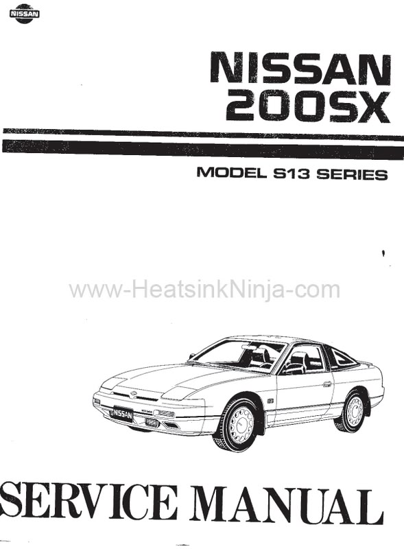
Complete service manual I bought this off ebay a while back, can't remember what I paid. Details 200sx with CA18DET.
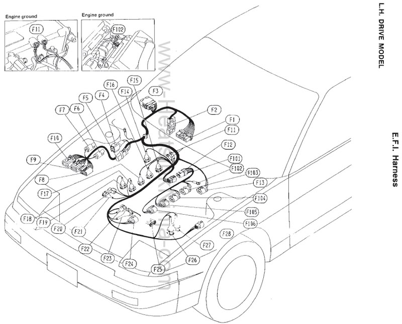
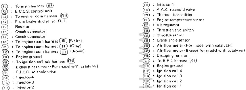
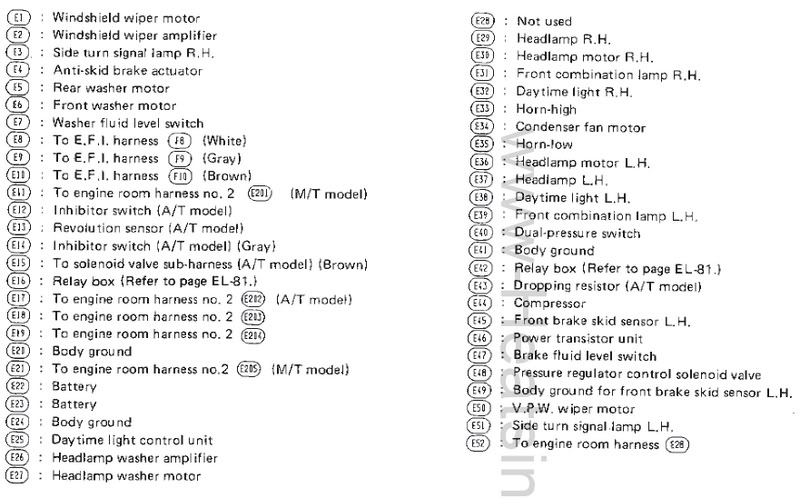
Complete description of all terminals from ECU to ca18det engine harness.
I was able to connect most of these. These control horn, flip up lights, turn signals, etc... I have more work to do in this area.
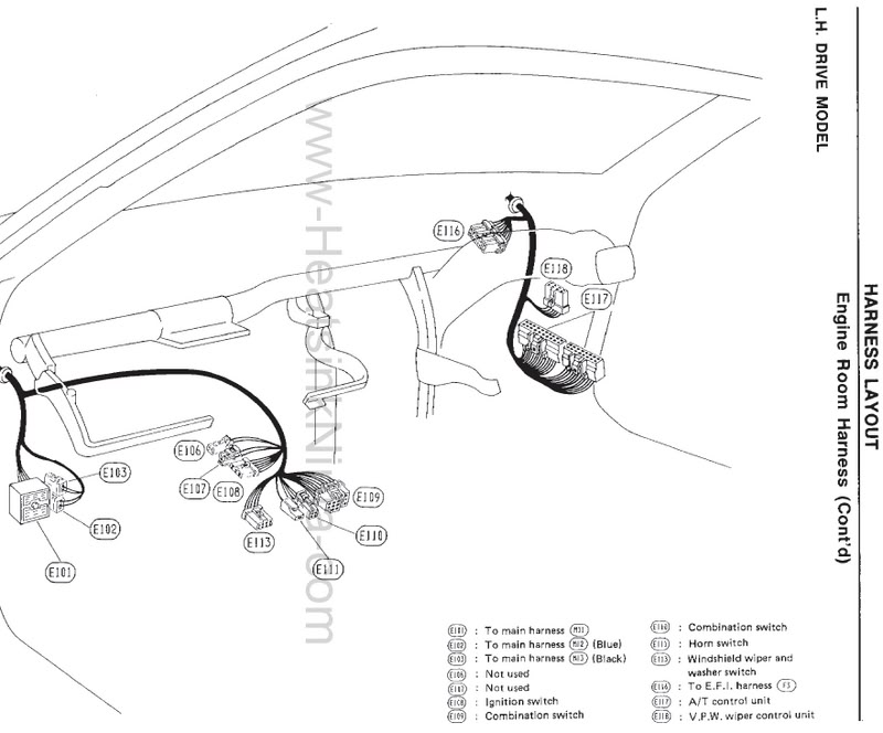
Simple enough.. Run wireness through firewall and connect ECU.
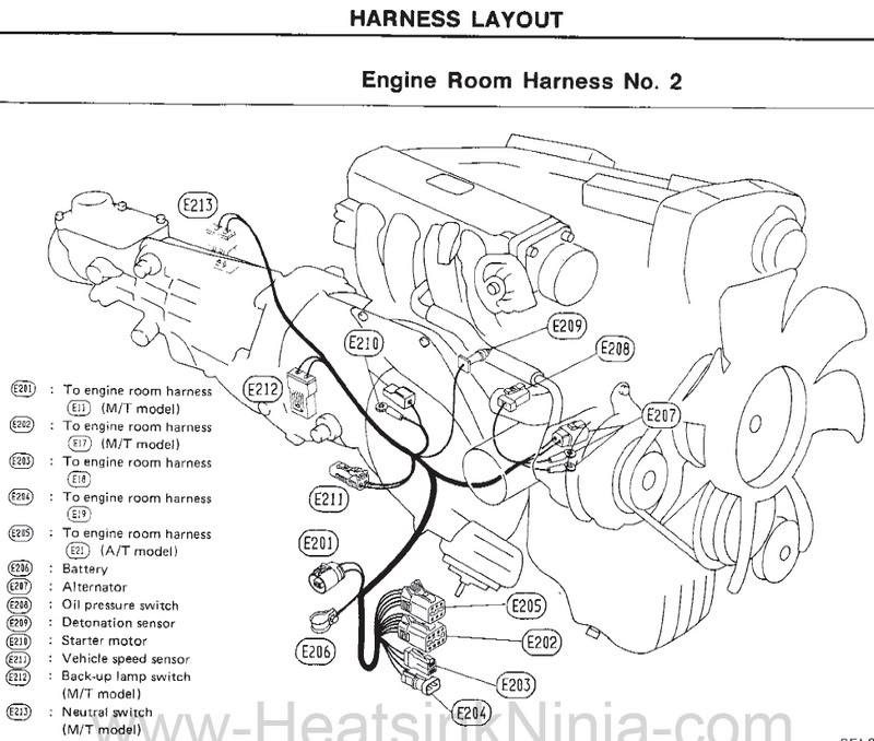
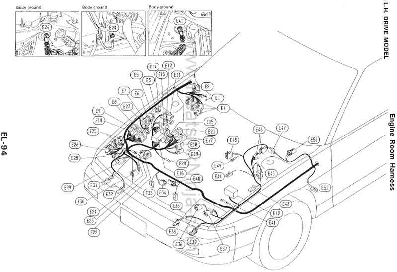
All terminals coming from this section of harness were all connected to the relay/fuse box (five total) on the right hand side. One connected on the side, one underneath, and three out the front near battery.
Well this is where I left off, only spend an hour or so looking around seeing what was what.. Tomorrow, I plan on spending more time on this. The info above should be of some help to anyone wiring the CA. Enjoy! (oh yea, my digital camera took a dump, and had to be sent out for repairs. Will take some pics once I get it back)
Complete service manual
I bought this off ebay a while back, can't remember what I paid. Details 200sx with CA18DET.Complete description of all terminals from ECU to ca18det engine harness.
I was able to connect most of these. These control horn, flip up lights, turn signals, etc... I have more work to do in this area.
Simple enough.. Run wireness through firewall and connect ECU.
All terminals coming from this section of harness were all connected to the relay/fuse box (five total) on the right hand side. One connected on the side, one underneath, and three out the front near battery.
Well this is where I left off, only spend an hour or so looking around seeing what was what.. Tomorrow, I plan on spending more time on this. The info above should be of some help to anyone wiring the CA. Enjoy! (oh yea, my digital camera took a dump, and had to be sent out for repairs. Will take some pics once I get it back)
12-29-2006, 08:06 PM
#59
Registered User
Thread Starter
Join Date: Feb 2005
Location: Binghamton, NY
Posts: 232
Haven't spent much time with the wiring. Kinda not wanting to do it, so I'm draggin **** on this part. My motor shipped with the right hand drive wire harness. This puts the MAF sensor, O2 sensor, and three other terminals for igniter assembly on the wrong side of the engine bay. I'm currently in the process of lengthening each wire one by one to go along the firewall to its needed area. There is prolly a better method of doing this, but this is the route I'm going.
I've removed all the loom, and heat wrap from the protective rubber grommet that leads through the firewall to tip of the other end of the harness. I bought 25' spools of 18, 16, 14, and 12 gauge wire that are needed in the lengthening. Plus, picked up some heat shrink, splice clips, and a good splice clip tool (not a cheap stereo all in one tool) to mate up the wires. Finally, once I'm done, each wire will need to be rewrapped in heat shielding and loom... fun, fun.
SS Autochrome 3" dump pipe. Seems to be decent, only concern is that the o2 sensor bung appears to be made of copper. Not sure how this may affect things over time.
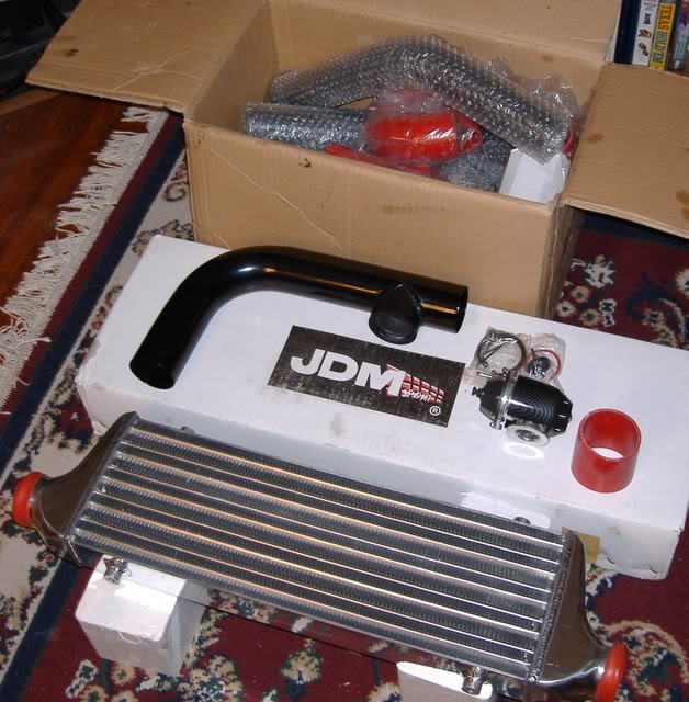
Intercooler, piping (2 1/2"), and BOV also arrived this week. It came well packed, not one bent fin on it, and appears to be well made. This also was an ebay special, should handle what I'm throwing at it.
This is it for now, I'm logging what I'm doing with the wiring. If it works for me, I'll post a step by step process of what I did.
That's it for now, happy holidays!
I've removed all the loom, and heat wrap from the protective rubber grommet that leads through the firewall to tip of the other end of the harness. I bought 25' spools of 18, 16, 14, and 12 gauge wire that are needed in the lengthening. Plus, picked up some heat shrink, splice clips, and a good splice clip tool (not a cheap stereo all in one tool) to mate up the wires. Finally, once I'm done, each wire will need to be rewrapped in heat shielding and loom... fun, fun.
SS Autochrome 3" dump pipe. Seems to be decent, only concern is that the o2 sensor bung appears to be made of copper. Not sure how this may affect things over time.
Intercooler, piping (2 1/2"), and BOV also arrived this week. It came well packed, not one bent fin on it, and appears to be well made. This also was an ebay special, should handle what I'm throwing at it.
This is it for now, I'm logging what I'm doing with the wiring. If it works for me, I'll post a step by step process of what I did.
That's it for now, happy holidays!
Last edited by trevr; 12-29-2006 at 08:11 PM.