My S13 SR20DET Prep
 10-17-2008, 02:53 PM
#241
Contributing Member
Thread Starter
Join Date: Sep 2002
Location: Starkville, MS.
Posts: 1,192
Gauges
I wired up my gauges today, I'm not good at wiring but I did some research and I think I have it figured out but if anyone sees something that I need to change then by all means chime in.
Tools needed:
Wire cutters
18 gauge wire
16-14 female connectors
16-14 male connectors
16-14 butt connectors
16-14 ring terminals
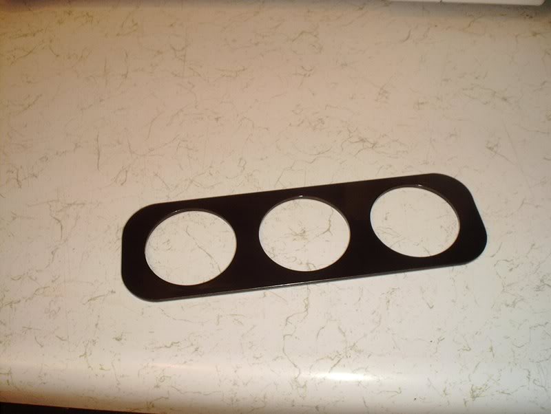
I ditched the A-pillar gauge pod for the A/C vent bezel. I wanted to keep things as OEM as possible and thought about putting the gauges in the glovebox but they really need to be where I can see them at a glance.
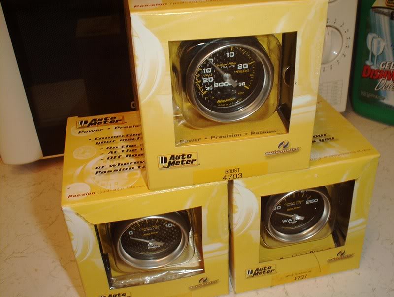
The three gauges that I chose were BOOST, OIL PRESSURE and WATER TEMP.
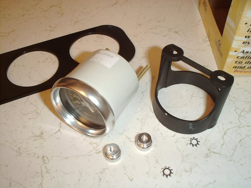
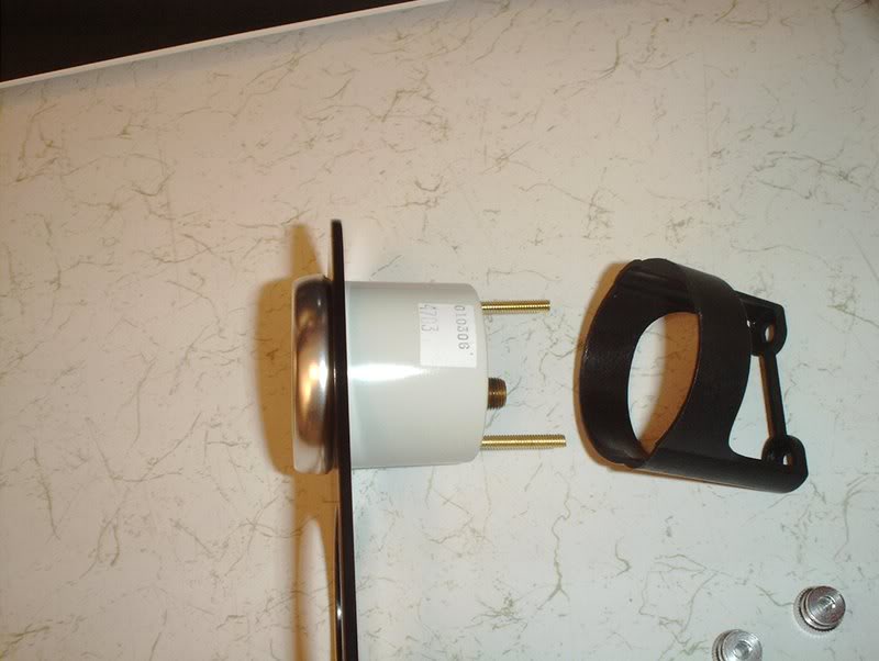
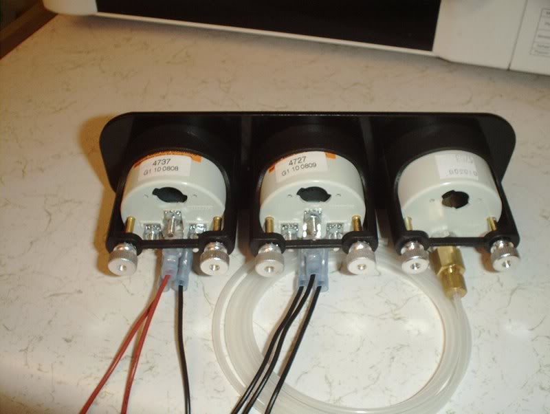
I first mounted the gauges using the supplied nuts and mounting pod thingy.
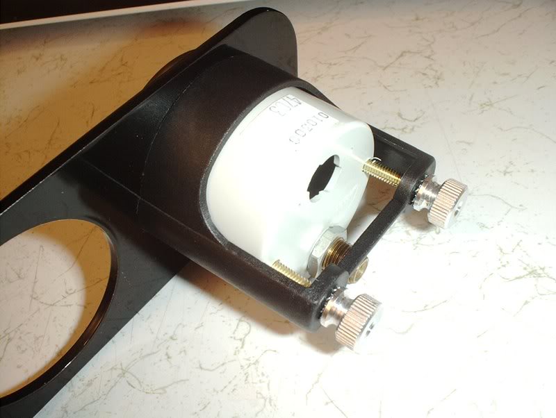
Mounted.
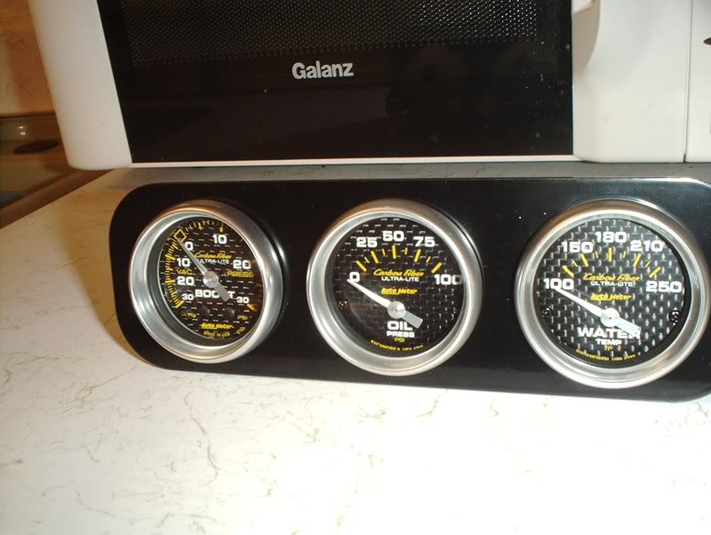
All three mounted.
I started with the BOOST gauge which seems to be relatively simple.
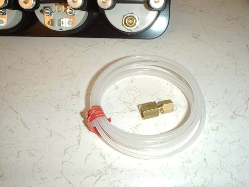
Here is the supplied hardware.
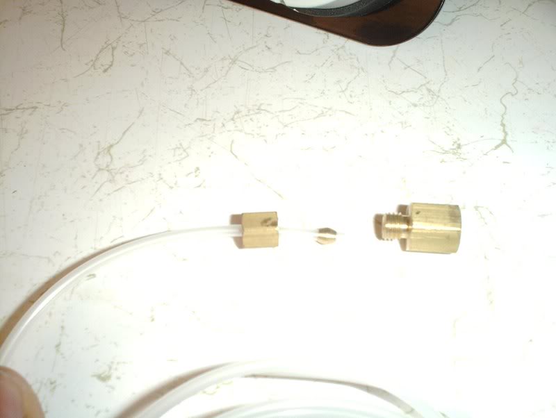
Take the nylon line, the compression nut, the ferule and the adapter...
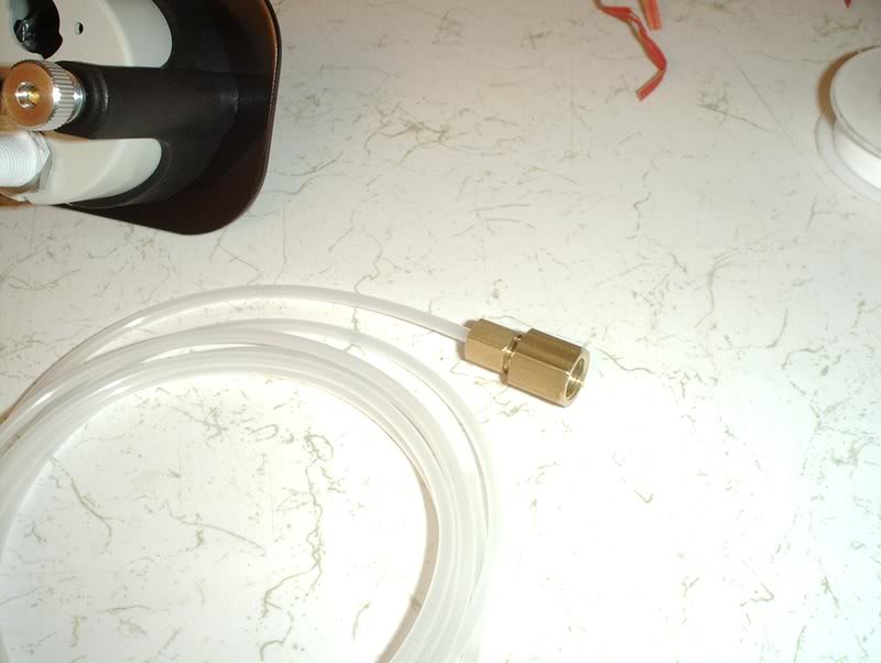
and screw them together to the point where it's tight and the nylon line is secure and can't be pulled out but do not overtighten!!!
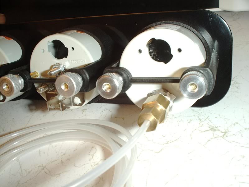
Put some teflon tape on the adapter threads and screw it into the BOOST gauge and again do not overtighten!!!
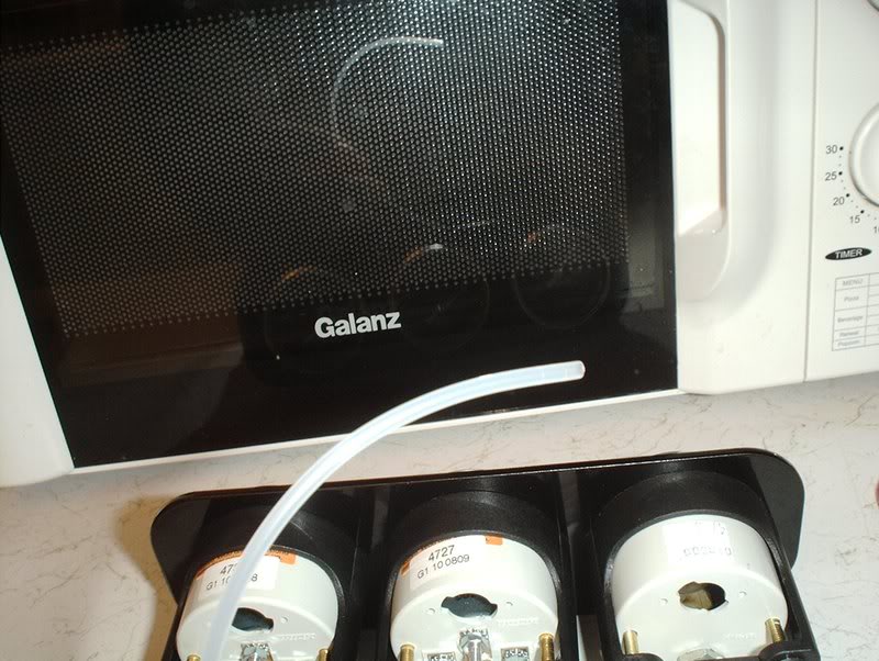
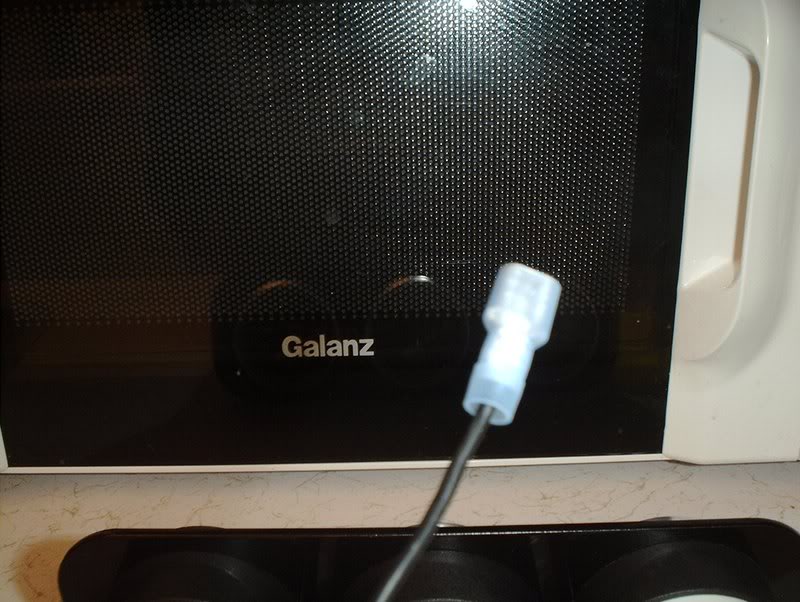
The other end of the nylon fitting will go through a hole of your choice in the firewall...
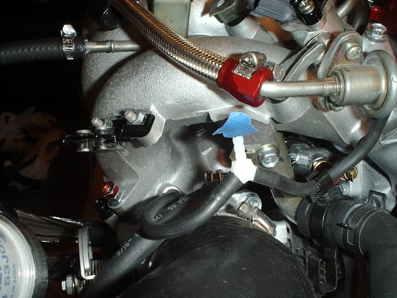
and get connected to this T-fitting on the line between the top left port of the throttlebody and the fuel pressure regulator.
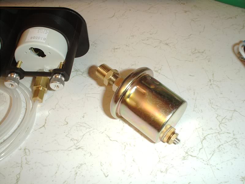
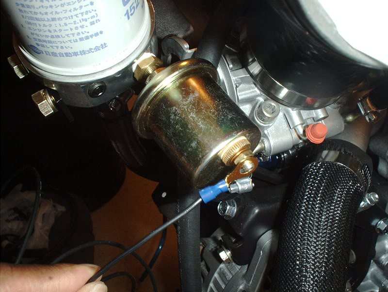
Next, I moved on to the OIL TEMP gauge. This is the OIL TEMP sender unit.
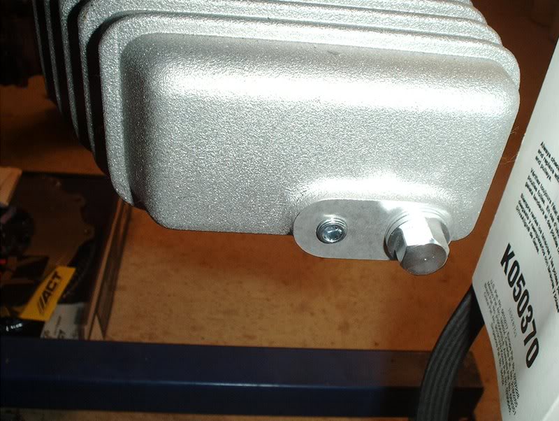
If you have a Greddy oil pan, you can mount the OIL TEMP sender here.
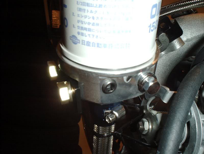
If you have a Greddy oil filter relocation kit, you can mount the sender unit here. I chose to use the oil filter.
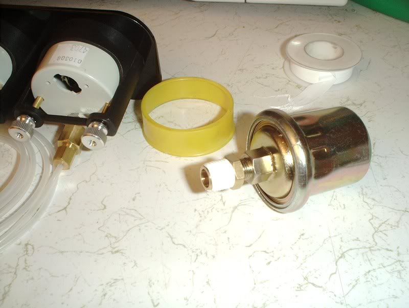
Put some teflon tape on the threads...
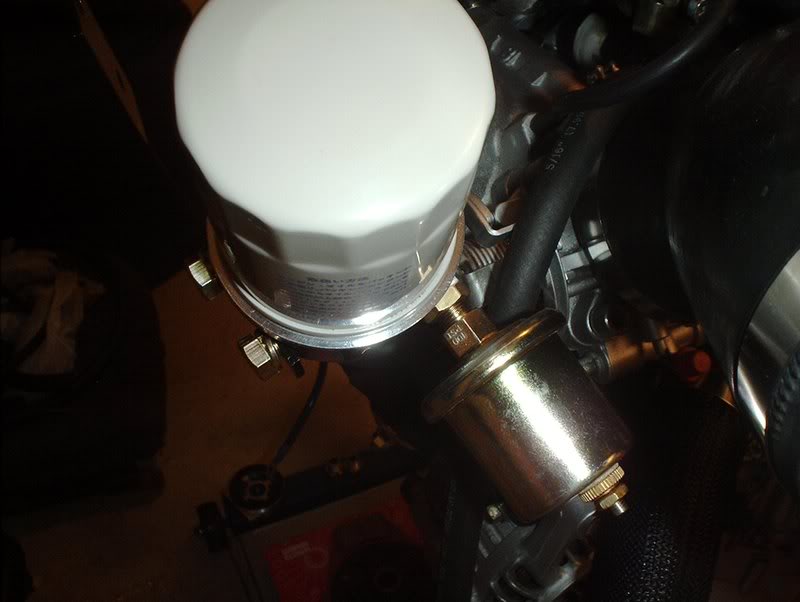
and insert into the kit.
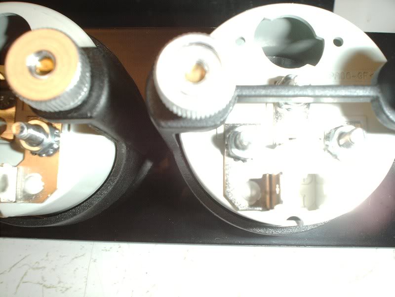
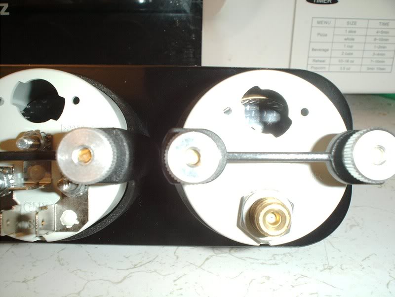
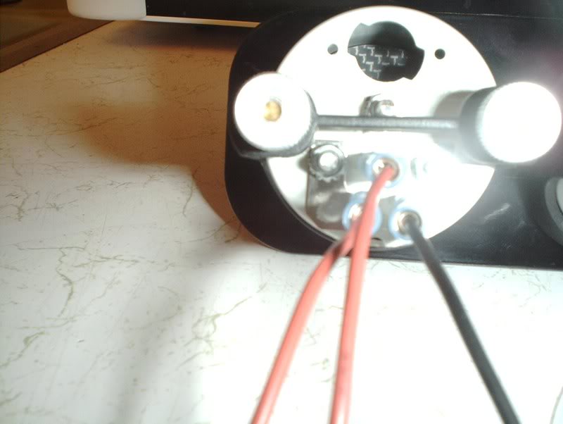
For the wiring of the OIL TEMP gauge, the back of the gauge has three terminals:
S-to sender
GND-ground
I-to 12V ignition switch or other switched 12V source.
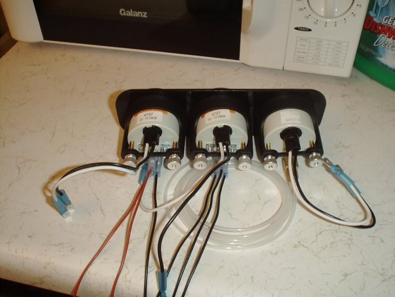
There are posts for ring terminals or female connectors, I chose the female connectors.
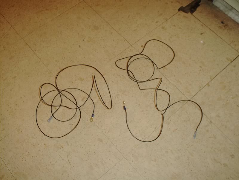
As far as how much wire I'm using, I'm just ball parking it. It's easier to take away than to add yes. I cut about 5 ft. for the S-sender and GND-ground.
Put a female connector on and crimp.
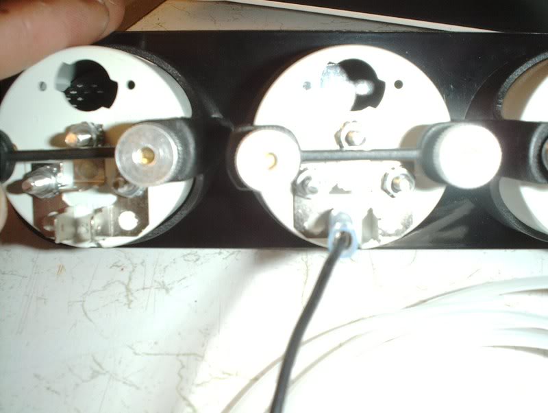
Place it on the S terminal.
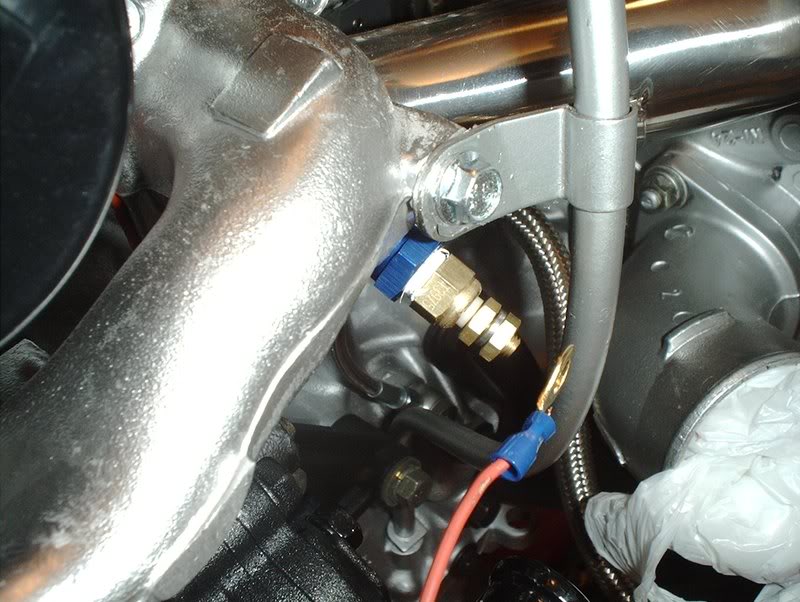
The other end, on swap day, will get ran through the firewall on the passenger side and get connected here on the OIL TEMP sender unit with a ring terminal.
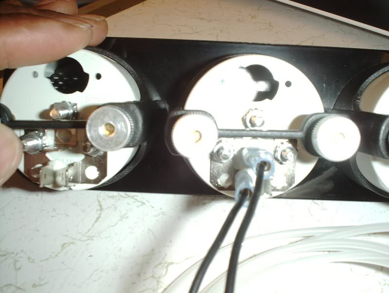
For the GND, put a female connector here...
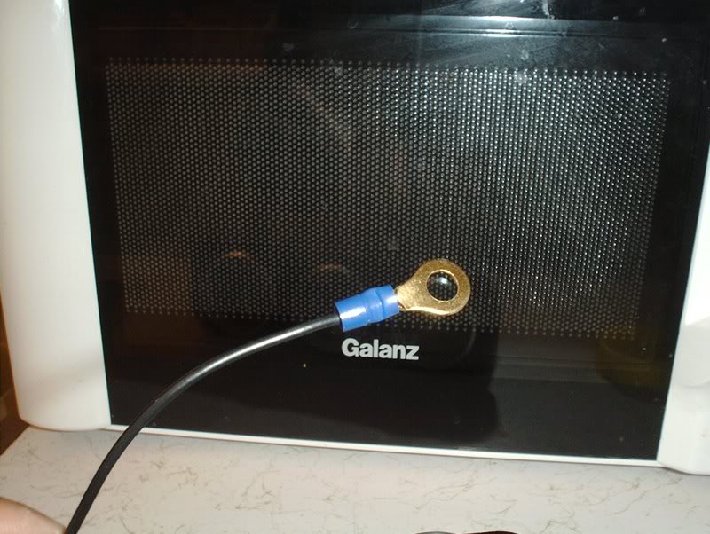
and for the other end, connect a ring terminal. Run the ring terminal through the same spot in the firewall. The instructions say to put the ground near the sender unit so I'll probably bolt it to the shock tower where the alternator and starter grounds are.
For I-ignition, I placed a female connector and I'm going to splice the other end in either the radio harness or the cigarette lighter harness for my 12V switched power source.
On to the WATER TEMP gauge. It has the same terminals as the OIL TEMP gauge so the wiring is basically the same.
Probably excessive but I cut about 8 ft. of wire for the S and GND wires here. Since this sender unit is on the exhaust manifold side of the engine, I'm going to run them in a spot away from the excessive heat. Place a female connector on the S terminal.
The wire will go through the firewall on the drivers side of the car. I'm going to run it through the same path as the hood latch cable that runs under the left fender and comes out in the hole near the drivers side fuse block. This path will allow you to avoid the heat coming from the exhaust manifold. Put a ring terminal on and connect here on the WATER TEMP sender unit.
For the GND, I put a female connector on the GND terminal and I'nm going to run the wire through the same spot as the S wire. The ground has to be close to the sender unit so I'll use a spot on the radiator support or near the fuse block.
For I-ignition, I cut a 2 to 3ft. wire and I'm going to use either the radio harness or the cig lighter harness.
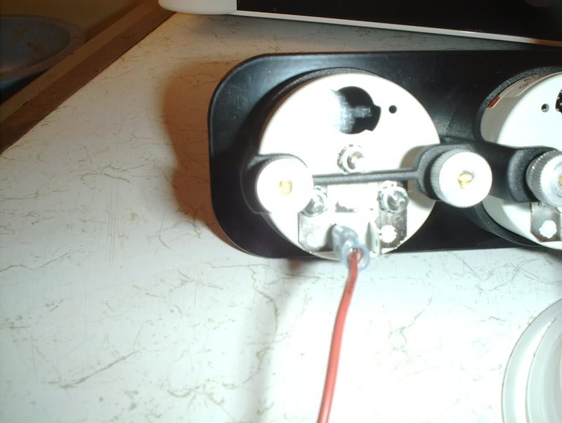
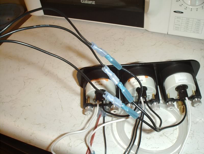
Lighting is next, especially if you want to see your gauges at night or if you have those smoked out gauges. I put the male 16-14 connectors on for the 18 gauge wire.
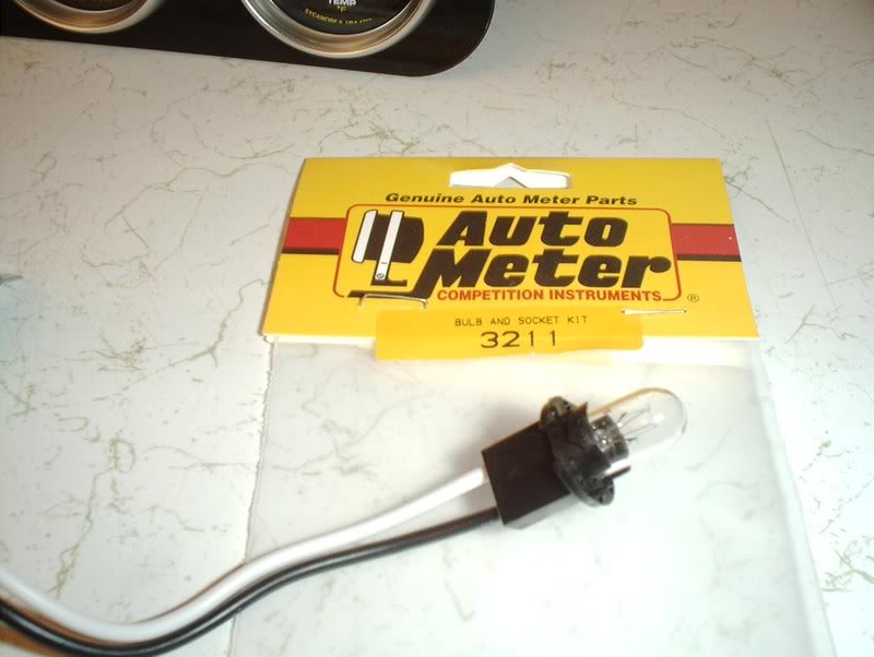
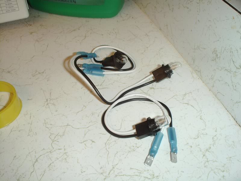
Funny thing, the OIL TEMP AND WATER TEMP gauges that I recently purchased came with the bulb sockets but the BOOST gauge that I bought some time ago did not so I had to track down a bulb. The part# is 3211, only thing is this bulb socket doesn't twist and lock in like the others. I'm going to have to put something on the back to keep it from popping off.
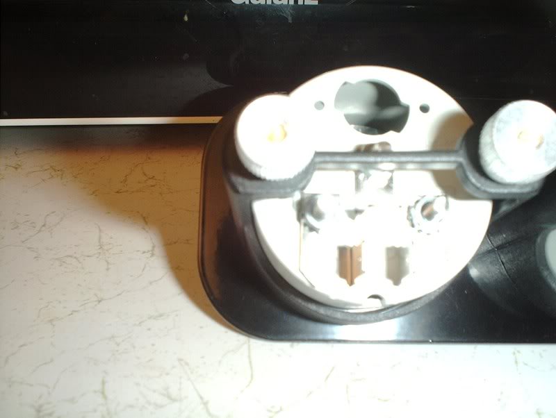
Take the bulb sockets...
and insert them.
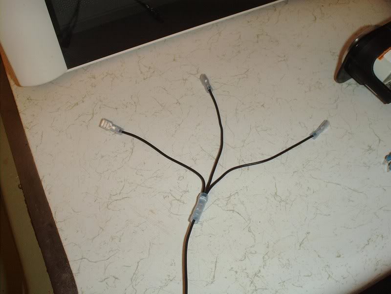
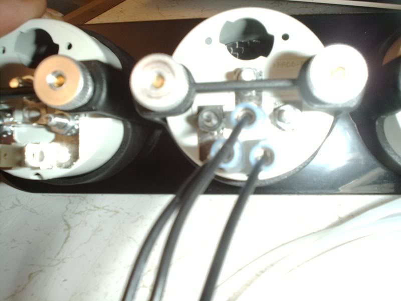
For the power wiring, I ran three short 3" inch wires together into the one wire. I'm thinking about soldering these instead of using the butt connectors here.
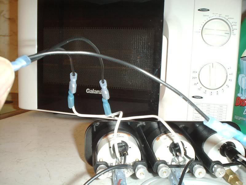
I connected them to the white(power) wires of the bulb sockets. The other end of the one wire that these converge on will get spliced to either the radio harness or the cig lighter.
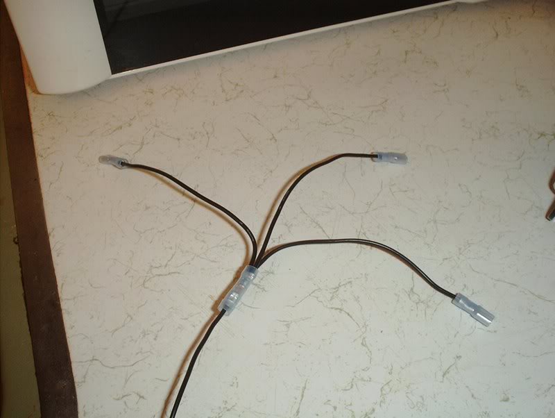
For the ground wiring, I connected three small pieces of wire into one...
and plugged the black ground wires up.
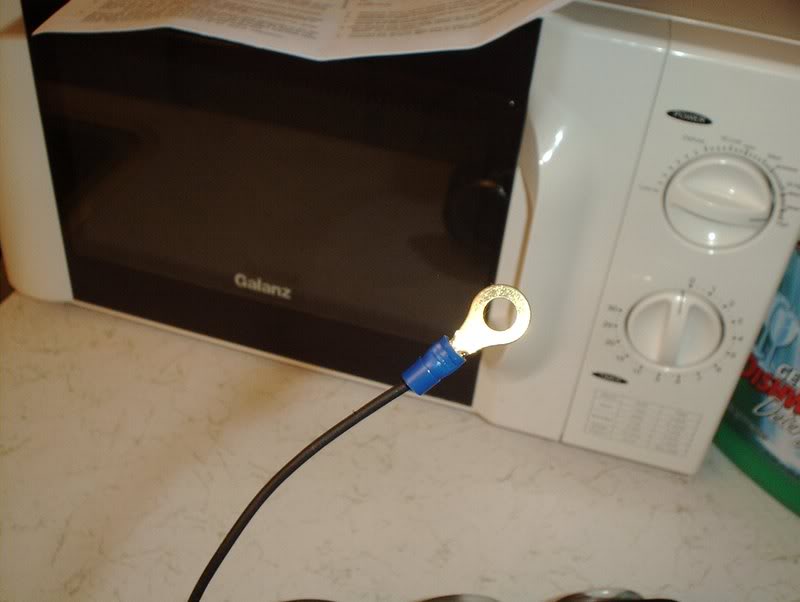
For the other end, I crimped on a ring terminal and will probably use one of the bolts on the shift boot dust cover for ground as this is bare chassis metal.
If anyone has any suggestions or changes then please let me know!
Tools needed:
Wire cutters
18 gauge wire
16-14 female connectors
16-14 male connectors
16-14 butt connectors
16-14 ring terminals
I ditched the A-pillar gauge pod for the A/C vent bezel. I wanted to keep things as OEM as possible and thought about putting the gauges in the glovebox but they really need to be where I can see them at a glance.
The three gauges that I chose were BOOST, OIL PRESSURE and WATER TEMP.
I first mounted the gauges using the supplied nuts and mounting pod thingy.
Mounted.
All three mounted.
I started with the BOOST gauge which seems to be relatively simple.
Here is the supplied hardware.
Take the nylon line, the compression nut, the ferule and the adapter...
and screw them together to the point where it's tight and the nylon line is secure and can't be pulled out but do not overtighten!!!
Put some teflon tape on the adapter threads and screw it into the BOOST gauge and again do not overtighten!!!
The other end of the nylon fitting will go through a hole of your choice in the firewall...
and get connected to this T-fitting on the line between the top left port of the throttlebody and the fuel pressure regulator.
Next, I moved on to the OIL TEMP gauge. This is the OIL TEMP sender unit.
If you have a Greddy oil pan, you can mount the OIL TEMP sender here.
If you have a Greddy oil filter relocation kit, you can mount the sender unit here. I chose to use the oil filter.
Put some teflon tape on the threads...
and insert into the kit.
For the wiring of the OIL TEMP gauge, the back of the gauge has three terminals:
S-to sender
GND-ground
I-to 12V ignition switch or other switched 12V source.
There are posts for ring terminals or female connectors, I chose the female connectors.
As far as how much wire I'm using, I'm just ball parking it. It's easier to take away than to add yes. I cut about 5 ft. for the S-sender and GND-ground.
Put a female connector on and crimp.
Place it on the S terminal.
The other end, on swap day, will get ran through the firewall on the passenger side and get connected here on the OIL TEMP sender unit with a ring terminal.
For the GND, put a female connector here...
and for the other end, connect a ring terminal. Run the ring terminal through the same spot in the firewall. The instructions say to put the ground near the sender unit so I'll probably bolt it to the shock tower where the alternator and starter grounds are.
For I-ignition, I placed a female connector and I'm going to splice the other end in either the radio harness or the cigarette lighter harness for my 12V switched power source.
On to the WATER TEMP gauge. It has the same terminals as the OIL TEMP gauge so the wiring is basically the same.
Probably excessive but I cut about 8 ft. of wire for the S and GND wires here. Since this sender unit is on the exhaust manifold side of the engine, I'm going to run them in a spot away from the excessive heat. Place a female connector on the S terminal.
The wire will go through the firewall on the drivers side of the car. I'm going to run it through the same path as the hood latch cable that runs under the left fender and comes out in the hole near the drivers side fuse block. This path will allow you to avoid the heat coming from the exhaust manifold. Put a ring terminal on and connect here on the WATER TEMP sender unit.
For the GND, I put a female connector on the GND terminal and I'nm going to run the wire through the same spot as the S wire. The ground has to be close to the sender unit so I'll use a spot on the radiator support or near the fuse block.
For I-ignition, I cut a 2 to 3ft. wire and I'm going to use either the radio harness or the cig lighter harness.
Lighting is next, especially if you want to see your gauges at night or if you have those smoked out gauges. I put the male 16-14 connectors on for the 18 gauge wire.
Funny thing, the OIL TEMP AND WATER TEMP gauges that I recently purchased came with the bulb sockets but the BOOST gauge that I bought some time ago did not so I had to track down a bulb. The part# is 3211, only thing is this bulb socket doesn't twist and lock in like the others. I'm going to have to put something on the back to keep it from popping off.
Take the bulb sockets...
and insert them.
For the power wiring, I ran three short 3" inch wires together into the one wire. I'm thinking about soldering these instead of using the butt connectors here.
I connected them to the white(power) wires of the bulb sockets. The other end of the one wire that these converge on will get spliced to either the radio harness or the cig lighter.
For the ground wiring, I connected three small pieces of wire into one...
and plugged the black ground wires up.
For the other end, I crimped on a ring terminal and will probably use one of the bolts on the shift boot dust cover for ground as this is bare chassis metal.
If anyone has any suggestions or changes then please let me know!
Last edited by positron; 10-18-2008 at 04:44 PM.
 10-17-2008, 04:29 PM
#242
i had a autometer guage they are nice but kinda hard to see at night. anyway your getting close to the point that you need to install the motor b4 doing anything else. when do you plan on droping it in?
10-18-2008, 03:40 AM
#245
Contributing Member
Thread Starter
Join Date: Sep 2002
Location: Starkville, MS.
Posts: 1,192
10-18-2008, 04:45 PM
#246
Contributing Member
Thread Starter
Join Date: Sep 2002
Location: Starkville, MS.
Posts: 1,192
Bulb Sockets
The Autometer #3211 bulb socket that I got is the wrong one for this application, the twist and lock bulb sockets are part#3220. You could use the #3211 but you'll have to put something on the back like a strong tape or something to keep it from popping out of the gauge.
Last edited by positron; 10-27-2008 at 03:29 AM.
10-27-2008, 03:29 AM
#247
Contributing Member
Thread Starter
Join Date: Sep 2002
Location: Starkville, MS.
Posts: 1,192
Gas???
Couple questions on gasoline for this engine. Been searching old threads but I couldn't find it. What type of gas do I run on this engine? Also, the car has been sitting up since I yanked the engine back in November so do I need to do anything with the gas that's left in it? I believe it still has less than half a tank of 93 left in it.
10-27-2008, 01:40 PM
#249
yeaup SR is a standard turbo motor give it 93 and it will be happy as with any turbo motor.. great progress brother.. i don't post a lot but i see you going man.
great contribution to this forum man.
great contribution to this forum man.
 I'm gettin' there!
11-07-2008, 02:39 AM
I'm gettin' there!
11-07-2008, 02:39 AM
#253
Contributing Member
Thread Starter
Join Date: Sep 2002
Location: Starkville, MS.
Posts: 1,192
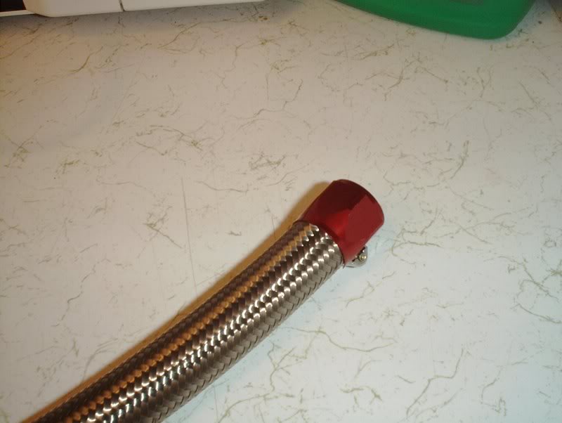
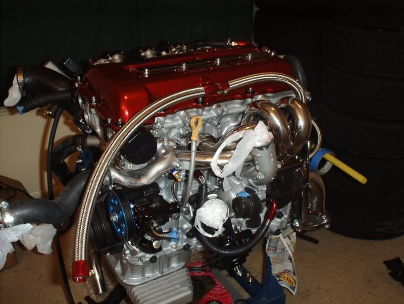
Steel Braided Catch Can Lines
I got some thermal wrap for this line but ditched it for a steel braided line instead.
Tools needed:
Flathead screwdriver
Dremel tool
Tape
Ruler
I got the parts from Jegs. A 3ft. section of -12AN steel braided hose
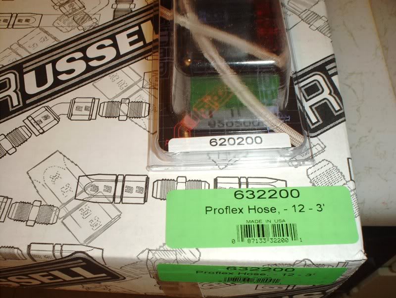
part#632200...
and two sets of -12AN hose fittings part# 620200.
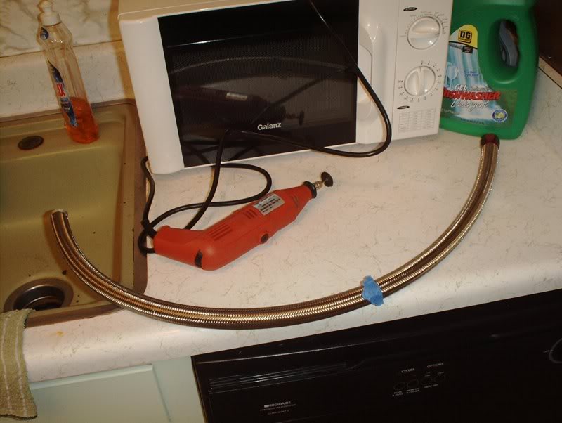
The hose that comes from the rear of the block to the T fitting is exactly 15 and 3/4 inches. I taped it off and used a dremel to cut the hose. What is left over is just enough to reach your catch can or intake hose if you don't have a catch can.
Tools needed:
Flathead screwdriver
Dremel tool
Tape
Ruler
I got the parts from Jegs. A 3ft. section of -12AN steel braided hose
part#632200...
and two sets of -12AN hose fittings part# 620200.
The hose that comes from the rear of the block to the T fitting is exactly 15 and 3/4 inches. I taped it off and used a dremel to cut the hose. What is left over is just enough to reach your catch can or intake hose if you don't have a catch can.