S13 KA24DE Engine Removal
 12-16-2007, 09:59 PM
#1
Contributing Member
Thread Starter
Join Date: Sep 2002
Location: Starkville, MS.
Posts: 1,192
S13 KA24DE Engine Removal
I took some pictures to document the removal of my KA in preparation for my engine swap. I did this write-up to help anyone with little mechanical knowledge, like me  , who would be wanting to attempt to do an engine swap themselves in the future and are skeptical about the procedure. I'm not doing this myself because I don't want to spend the money to have a professional shop do it
  but because I have been building this car with my own hands, I've done the frontend conversion, suspension, climate, steering wheel, seats, brakes, exhaust, etc. and completing the engine swap myself would be the icing on the cake. I want this to be as complete as possible so if anyone notices something that I missed...please chime in and add to the write-up.
Tools needed:
Jack
Jackstands
Wrenchs
Socket wrench
Sockets(different sizes)
Hammer
Screwdrivers(flathead/phillips)
Needle nose pliers
Prybar
Drain pan
Line wrench 10mm
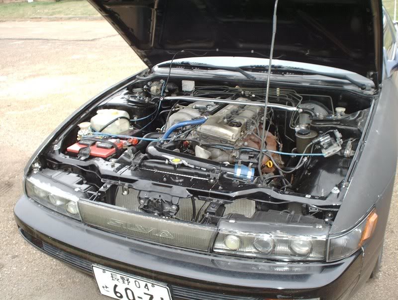
My car is a '93 240SX with a KA24DE engine. This isn't a complete write-up on removing the engine because my car doesn't have emissions or the A/C components so those of you with those will have to look elsewhere about how to handle those systems. I'm just a regular joe doing this swap in the driveway of my apartment with handtools and time.
The first thing I did was to relieve the fuel pressure so when I remove the fuel lines in the engine bay I won't have fuel squirting all over the place.
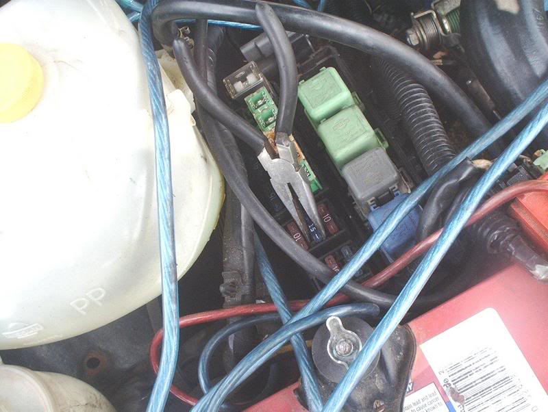
To relieve fuel pressure go to the engine bay and pull the fuel pump fuse 15A from the fuse block, loosen your fuel tank cap, crank the car and run it until it stalls out.
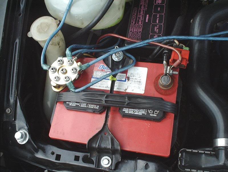
Next, I removed the battery cables and pulled the battery. You can put the fuel pump fuse back now.
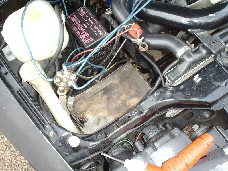
Done!
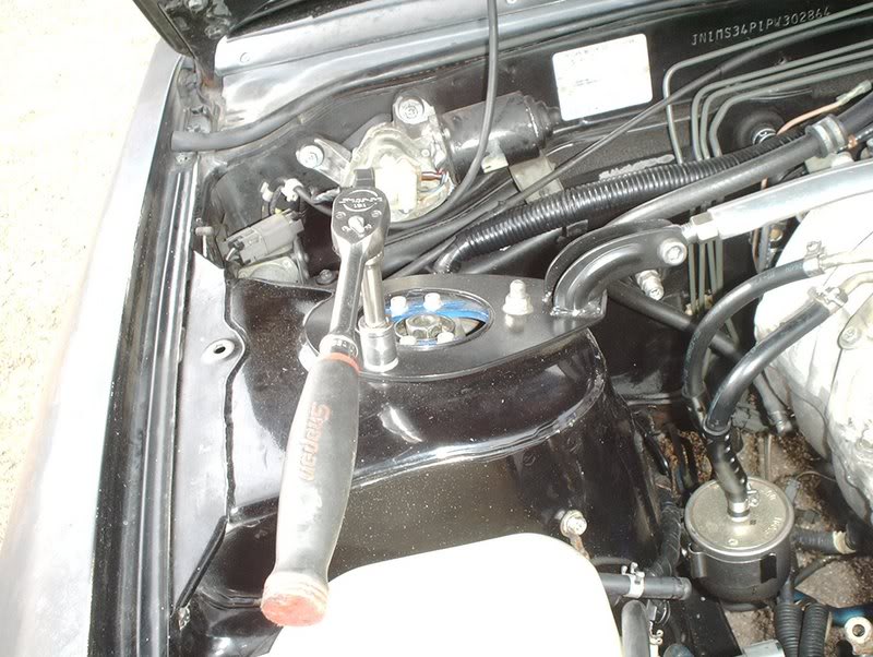
If you have a front strut tower bar now would be a good time to remove it as well. Six 14mm bolts.
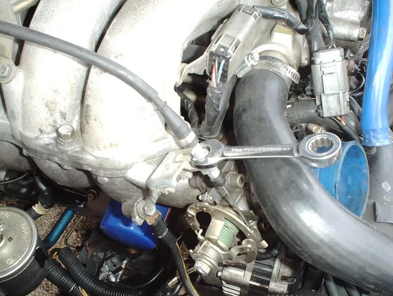
Use a 14mm wrench to loosen the throttle cable nut.
Done!

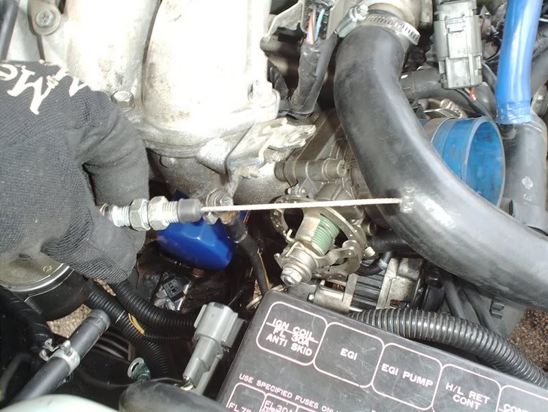
I removed the MAF plug from the MAF sensor.
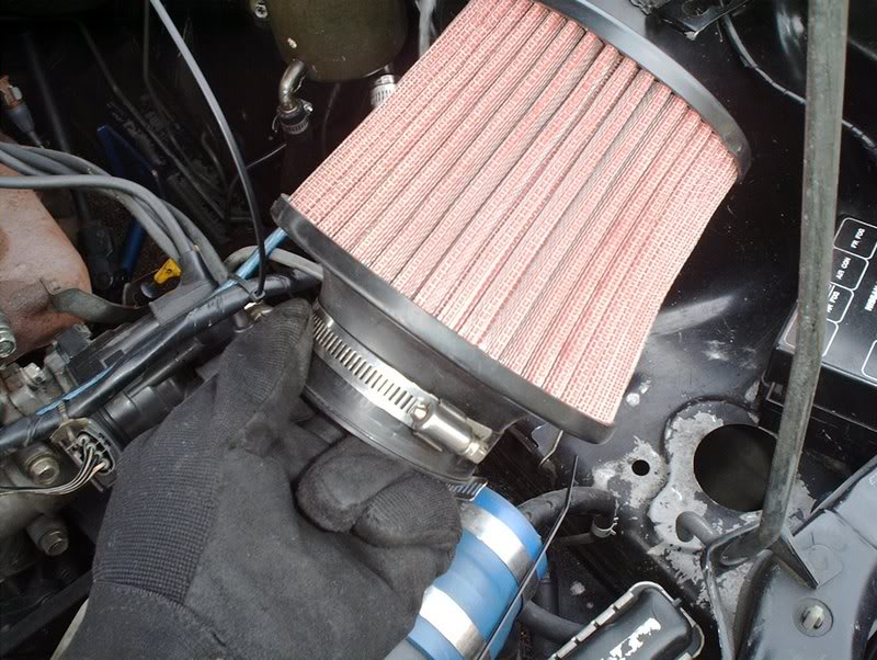
Then the air filter...
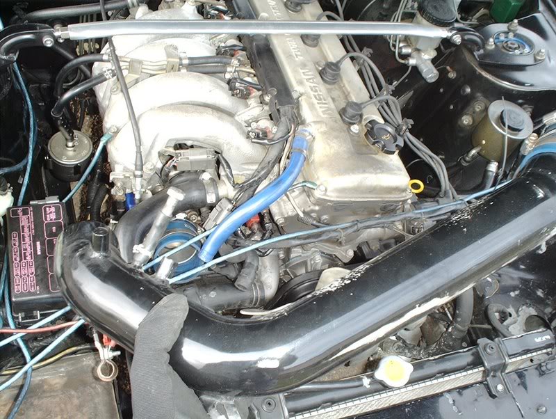
and the piping to free up some room.
Done!
After removing the battery, the throttle cable and the intake I concentrated on draining all my fluids, powersteering, transmission, oil, coolant and clutch.
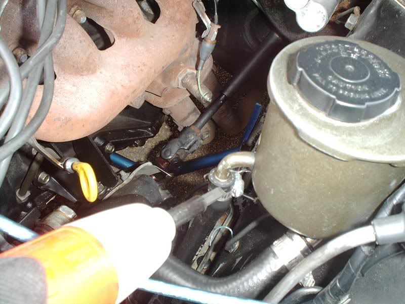
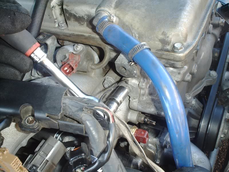
I began with the powersteering fluid by disconecting the two small hoses coming from the P/S resevoir...
and draining the fluid into a bottle.
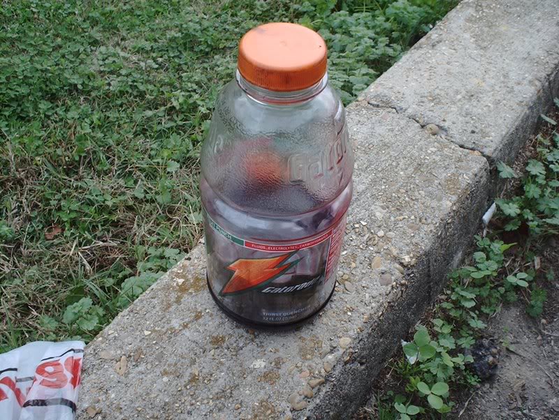
Done! Gatorade's newest flavor...P/S grape mango...have some!?
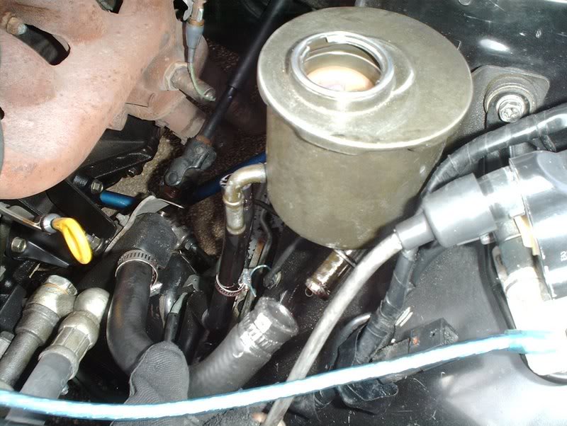
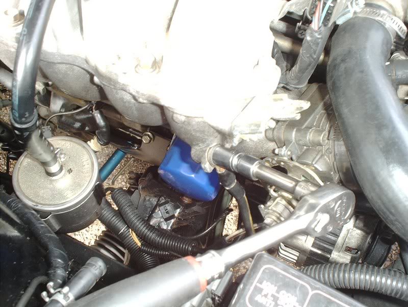
Of course there's some fluid remaining in the P/S pump and the steering rack so I just capped them off to prevent any spillage. Go ahead and remove the powersteering banjo bolt with a 23mm socket. Now you can take the P/S pressure hose off the P/S pump.
, who would be wanting to attempt to do an engine swap themselves in the future and are skeptical about the procedure. I'm not doing this myself because I don't want to spend the money to have a professional shop do it but because I have been building this car with my own hands, I've done the frontend conversion, suspension, climate, steering wheel, seats, brakes, exhaust, etc. and completing the engine swap myself would be the icing on the cake. I want this to be as complete as possible so if anyone notices something that I missed...please chime in and add to the write-up.Tools needed:
Jack
Jackstands
Wrenchs
Socket wrench
Sockets(different sizes)
Hammer
Screwdrivers(flathead/phillips)
Needle nose pliers
Prybar
Drain pan
Line wrench 10mm
My car is a '93 240SX with a KA24DE engine. This isn't a complete write-up on removing the engine because my car doesn't have emissions or the A/C components so those of you with those will have to look elsewhere about how to handle those systems. I'm just a regular joe doing this swap in the driveway of my apartment with handtools and time.
The first thing I did was to relieve the fuel pressure so when I remove the fuel lines in the engine bay I won't have fuel squirting all over the place.
To relieve fuel pressure go to the engine bay and pull the fuel pump fuse 15A from the fuse block, loosen your fuel tank cap, crank the car and run it until it stalls out.
Next, I removed the battery cables and pulled the battery. You can put the fuel pump fuse back now.
Done!
If you have a front strut tower bar now would be a good time to remove it as well. Six 14mm bolts.
Use a 14mm wrench to loosen the throttle cable nut.
Done!
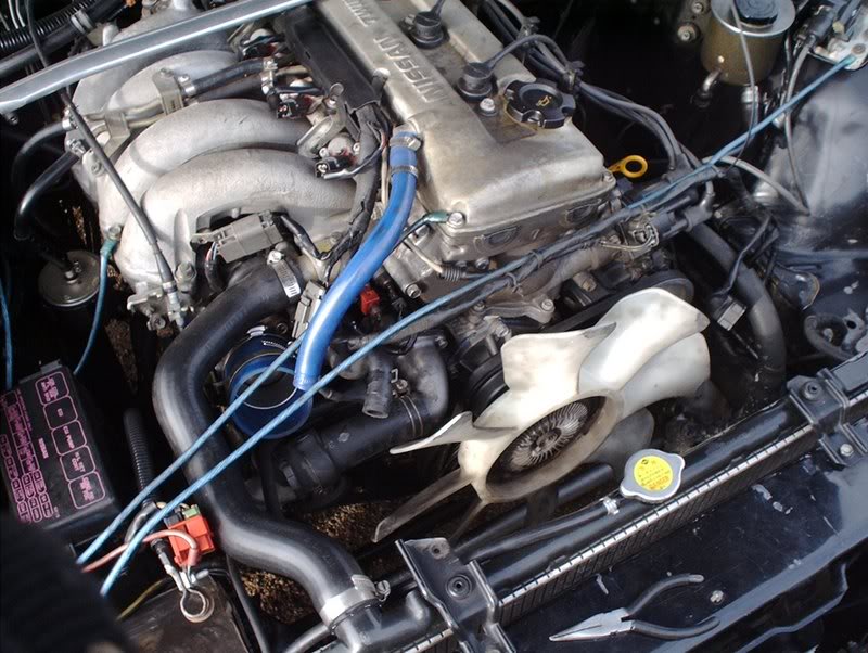
I removed the MAF plug from the MAF sensor.
Then the air filter...
and the piping to free up some room.
Done!
After removing the battery, the throttle cable and the intake I concentrated on draining all my fluids, powersteering, transmission, oil, coolant and clutch.
I began with the powersteering fluid by disconecting the two small hoses coming from the P/S resevoir...
and draining the fluid into a bottle.
Done! Gatorade's newest flavor...P/S grape mango...have some!?
Of course there's some fluid remaining in the P/S pump and the steering rack so I just capped them off to prevent any spillage. Go ahead and remove the powersteering banjo bolt with a 23mm socket. Now you can take the P/S pressure hose off the P/S pump.
Last edited by positron; 12-17-2007 at 01:20 AM.
 12-16-2007, 10:00 PM
#2
Contributing Member
Thread Starter
Join Date: Sep 2002
Location: Starkville, MS.
Posts: 1,192
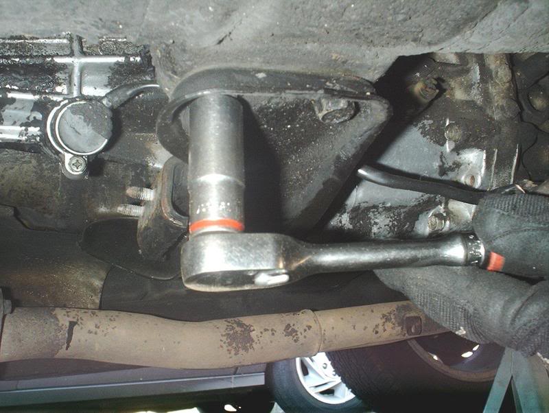
Now for the transmission fluid, jack the front of the car up and place jackstands in the appropriate places.
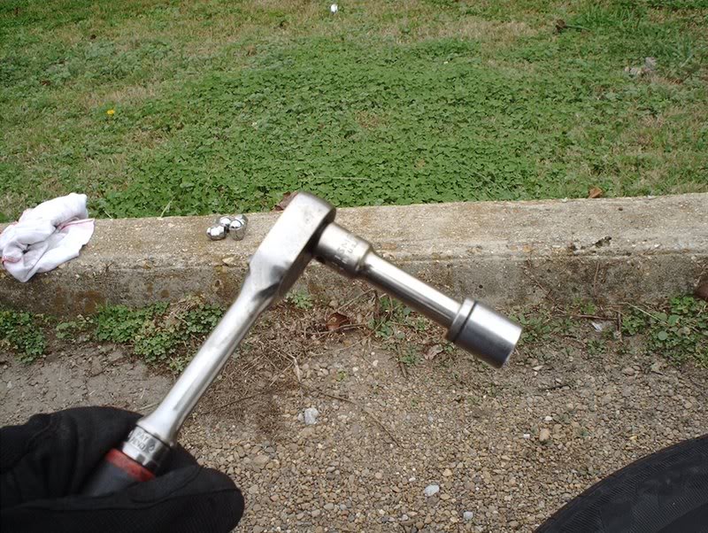
You'll need a socket wrench with a 3/8 adapter for the transmission drain plug.
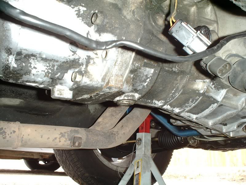
The transmission drain plug is located directly beneath the transmission.
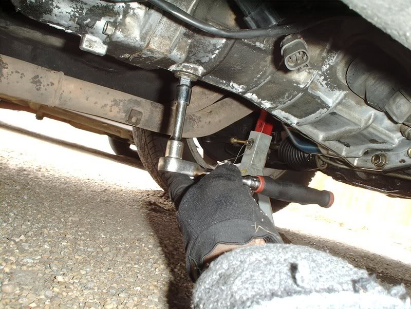
Insert the socket into the drain plug and remove it, be sure to have your drain pan ready to move into place to catch the flowing tranny fluid.
Done!
To drain the engine oil you need a 14mm socket.
Remove the oil pan drain plug....
and have your drain pan ready for the oil.
Done!
Now to drain the radiator coolant.
The radiator drain plug is located on the bottom corner of the right side of the radiator.
To remove the plug just use a phillipshead screwdriver.
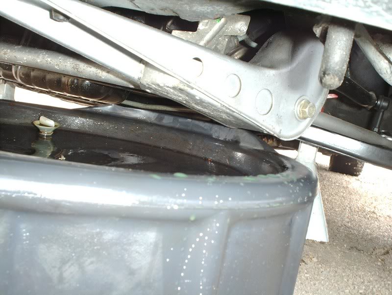
Drain the coolant out.
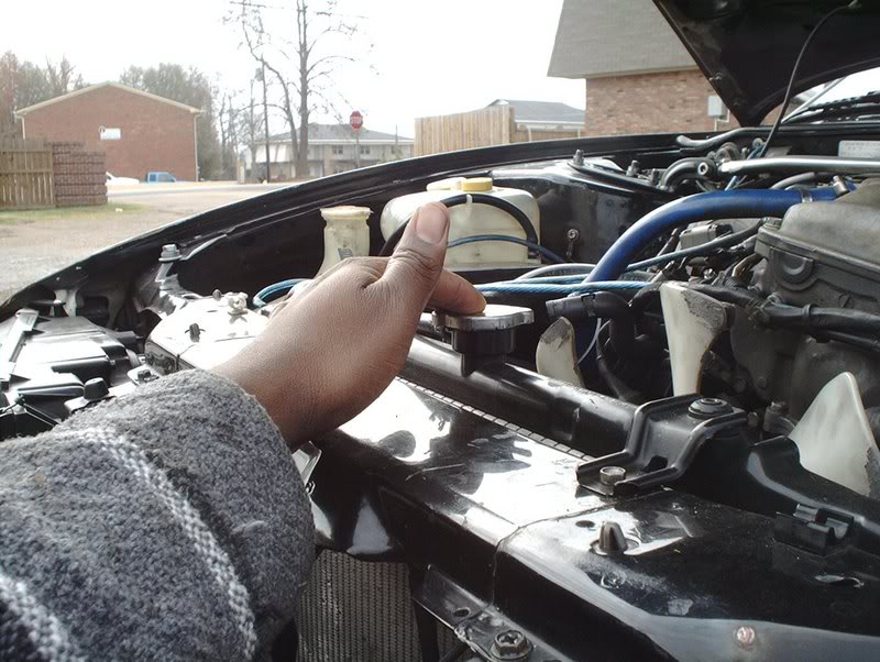
One interesting thing I noticed was that because of the pressure inside the radiator I could use the radiator cap to control how fast or slow the coolant flowed as it drained, just like the controls on a faucet.
Empty.
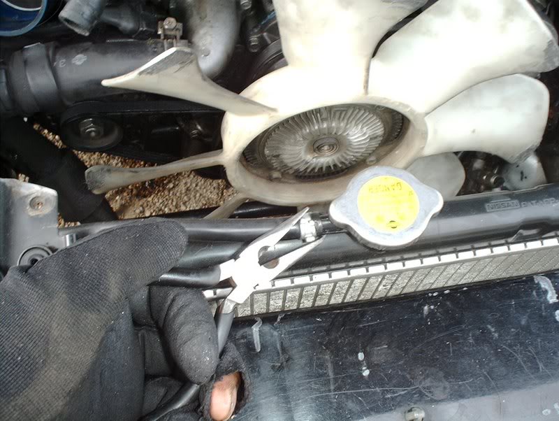
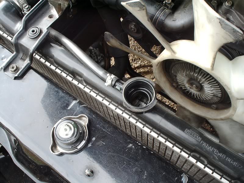
Next, use a pair of needle nose pliers to remove the hose for the coolant reserve tank.
You can let it drain off into the pan as well.
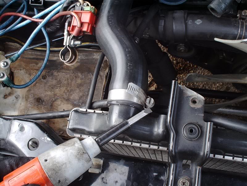
Now you need to remove the upper radiator hose.
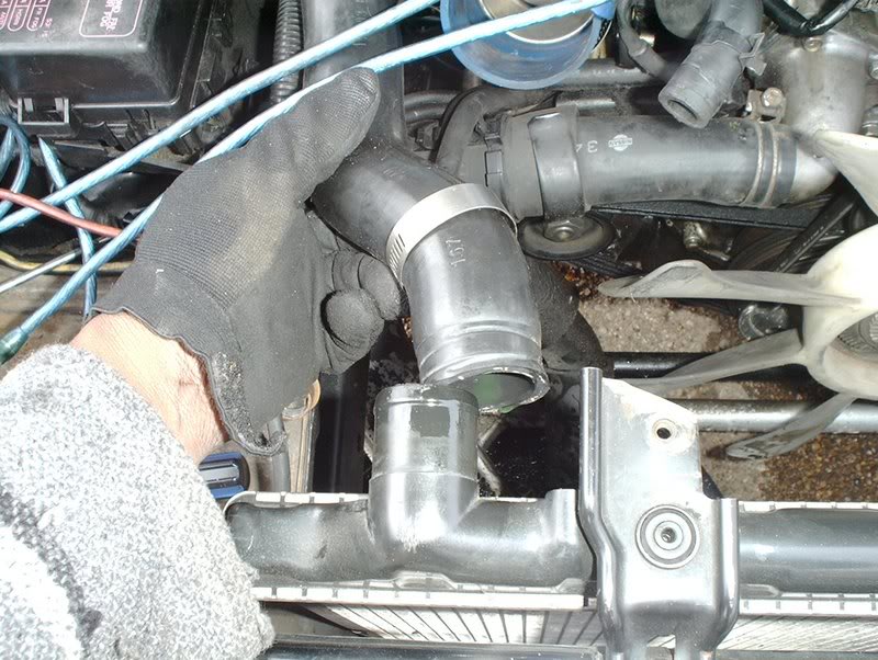
Done!
Remove the lower radiator hose.
Done!
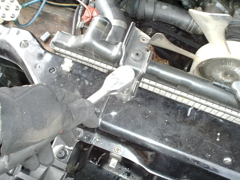
Next use a 10mm socket to remove both radiator brackets....
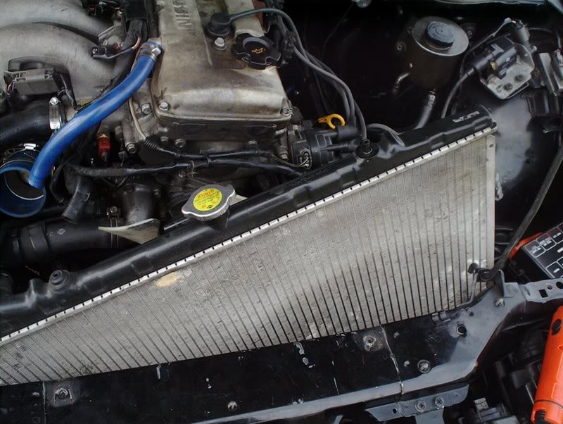
and now you can pull the radiator.
Finished with the rad.
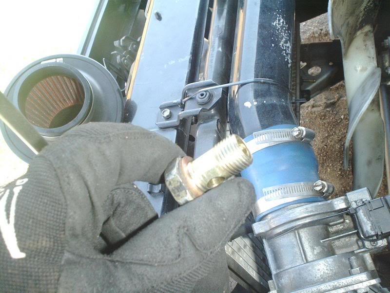
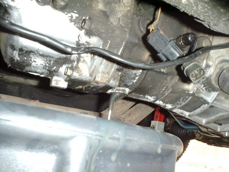
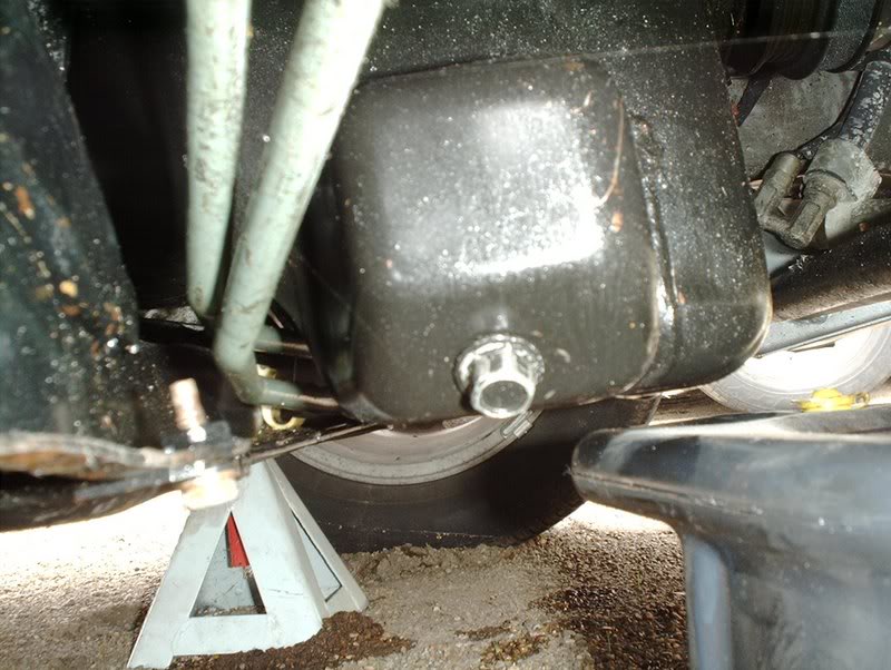
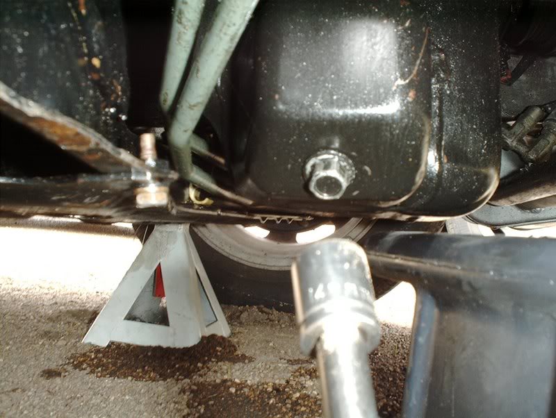
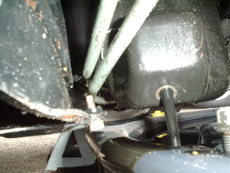
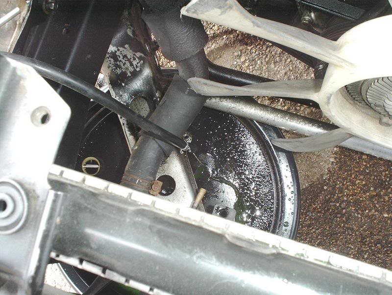
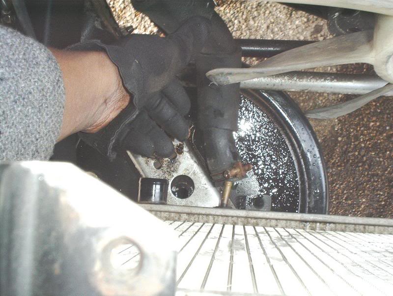
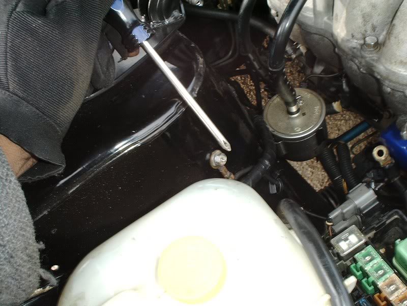
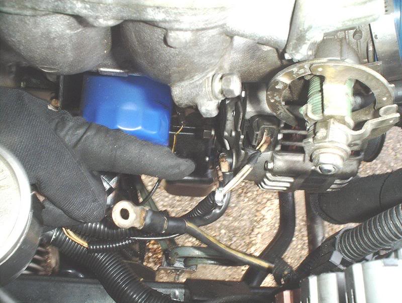
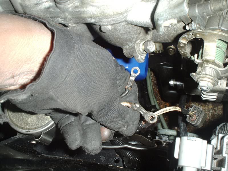
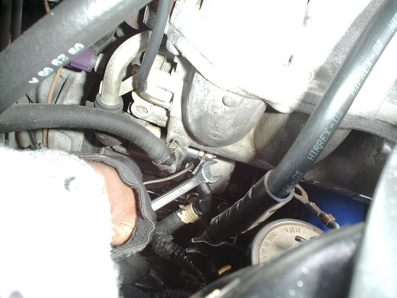
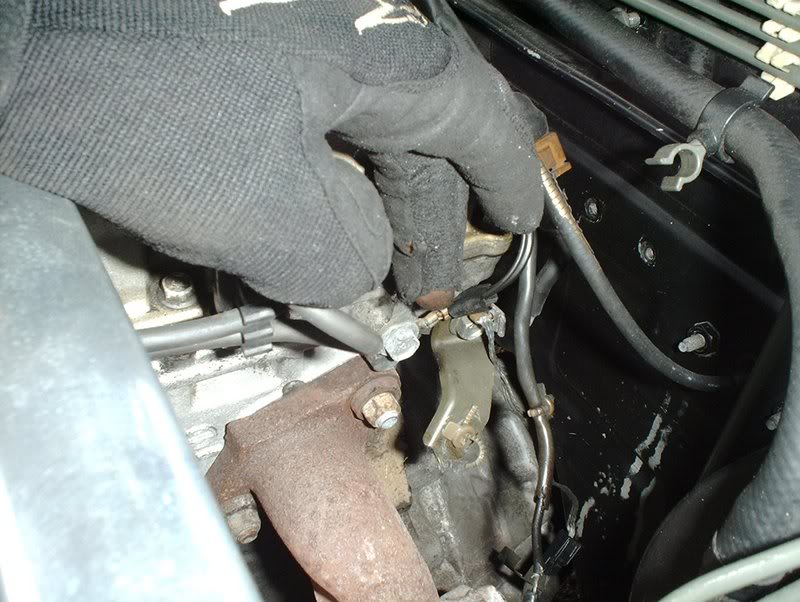
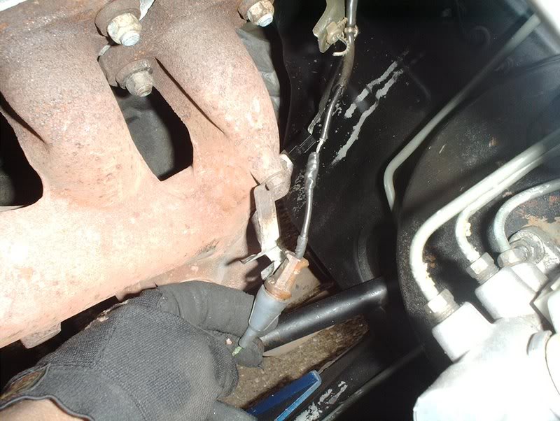
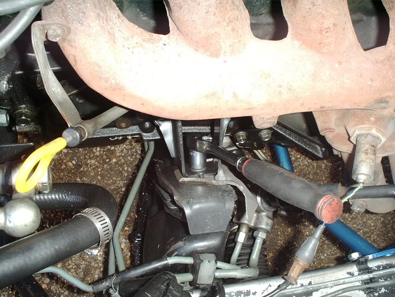
Finally you need to drain the clutch fluid by way of the clutch slave cylinder which is located on the bottom of the transmission.
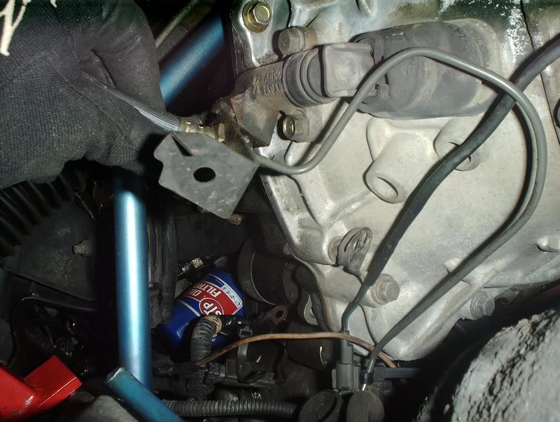
The clutch line is attached to the chassis of the car with this bracket which was not even attached on my car, not to mention the fubared way that my clutch hardline is kinked up. I'm gonna have to replace this hardline when I prep the engine bay, I don't like the "bendy straw" status of this hardline. The previous owner of this car was an idjot, yeah I mean id-jot!
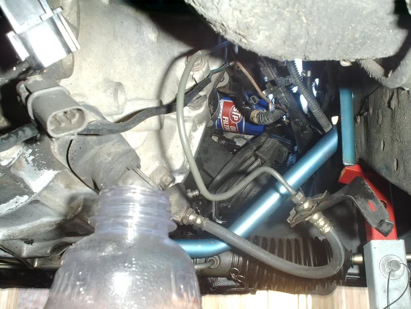
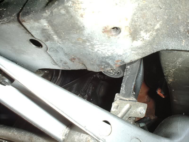
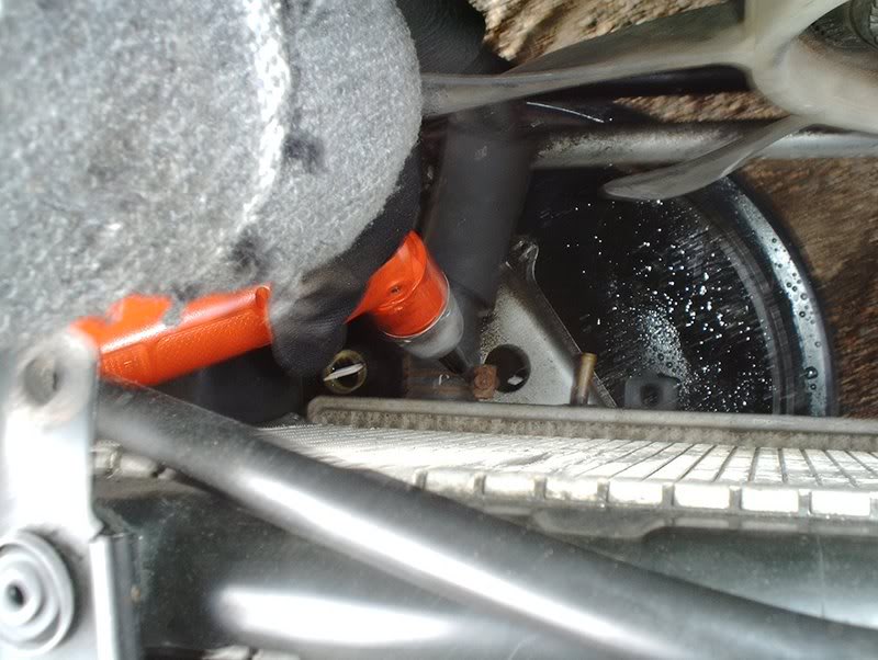
There is a bleeder screw on the side of the slave cylinder which can be used but since I am removing this engine and transmission I just disconnected the clutch line from the chassis hardline and drained the clutch fluid into a bottle.
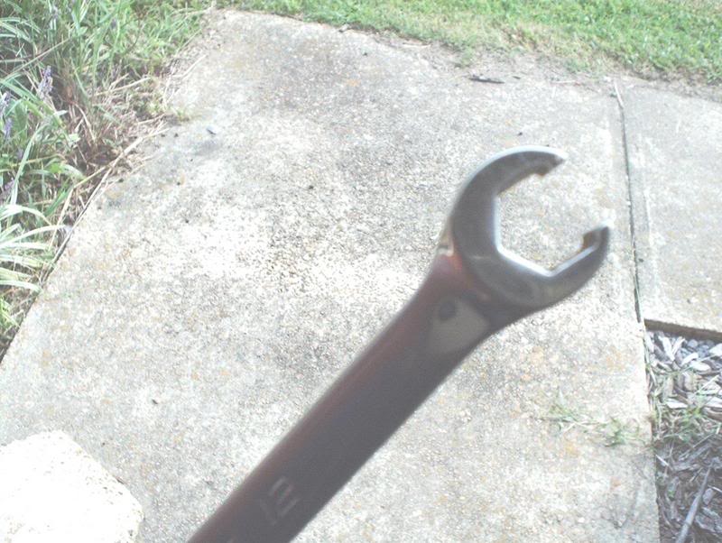
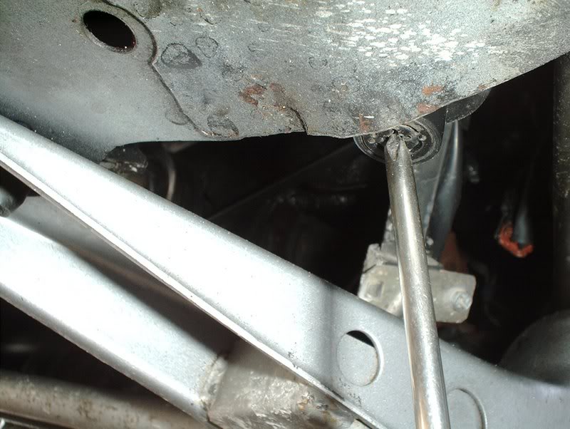
I used a 10mm line wrench to remove the clutch hardline from the clutch softline...god bless the line wrench!
You'll need a socket wrench with a 3/8 adapter for the transmission drain plug.
The transmission drain plug is located directly beneath the transmission.
Insert the socket into the drain plug and remove it, be sure to have your drain pan ready to move into place to catch the flowing tranny fluid.
Done!
To drain the engine oil you need a 14mm socket.
Remove the oil pan drain plug....
and have your drain pan ready for the oil.
Done!
Now to drain the radiator coolant.
The radiator drain plug is located on the bottom corner of the right side of the radiator.
To remove the plug just use a phillipshead screwdriver.
Drain the coolant out.
One interesting thing I noticed was that because of the pressure inside the radiator I could use the radiator cap to control how fast or slow the coolant flowed as it drained, just like the controls on a faucet.
Empty.
Next, use a pair of needle nose pliers to remove the hose for the coolant reserve tank.
You can let it drain off into the pan as well.
Now you need to remove the upper radiator hose.
Done!
Remove the lower radiator hose.
Done!
Next use a 10mm socket to remove both radiator brackets....
and now you can pull the radiator.
Finished with the rad.
Finally you need to drain the clutch fluid by way of the clutch slave cylinder which is located on the bottom of the transmission.
The clutch line is attached to the chassis of the car with this bracket which was not even attached on my car, not to mention the fubared way that my clutch hardline is kinked up. I'm gonna have to replace this hardline when I prep the engine bay, I don't like the "bendy straw" status of this hardline. The previous owner of this car was an idjot, yeah I mean id-jot!
There is a bleeder screw on the side of the slave cylinder which can be used but since I am removing this engine and transmission I just disconnected the clutch line from the chassis hardline and drained the clutch fluid into a bottle.
I used a 10mm line wrench to remove the clutch hardline from the clutch softline...god bless the line wrench!
Last edited by positron; 12-17-2007 at 01:30 AM.
12-16-2007, 10:01 PM
#3
Contributing Member
Thread Starter
Join Date: Sep 2002
Location: Starkville, MS.
Posts: 1,192
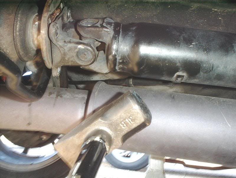
That concludes the draining of the fluids, now I'm going to disconnect the driveshaft. Jack the rear of the car up and place your jackstands.
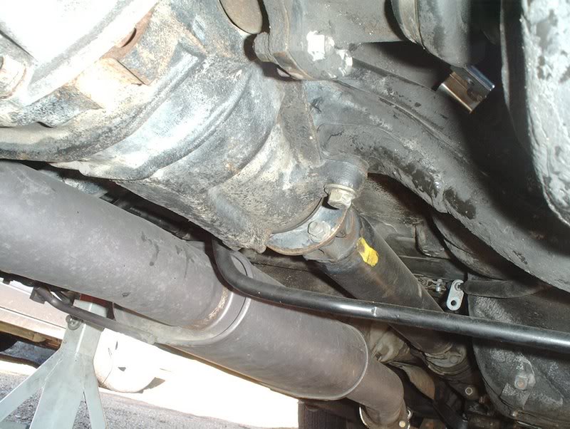
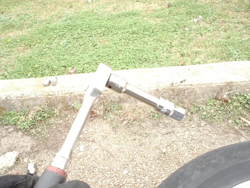
The driveshaft. To remove it you need a 14mm socket or wrench.
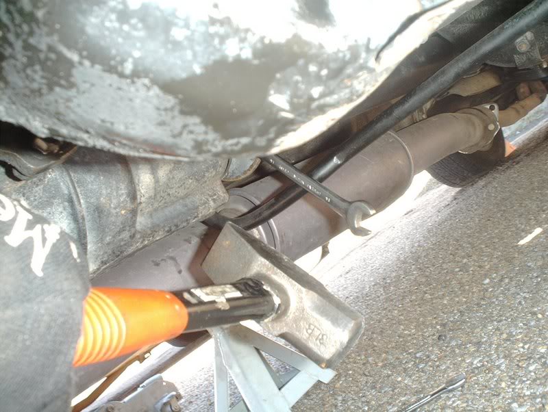
I ran into a problem here. I had a 14mm socket but it would not fit flush against the shaft because of its shape. I couldn't get the socket on either side of the driveshaft bolts so I used a 14mm wrench which I could get to sit flush and hit the end of the wrench with my 3lb. hammer(Mjollnir) to bust the nuts loose on the driveshaft bolts.
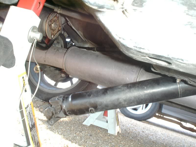
After you get each nut loose on the driveshaft, you need to go to the inside of the car and let the ebrake down...
so you can spin the driveshaft with your hands which will allow you to move the next driveshaft bolt/nut into position for removal. Let the ebrake back up so the shaft won't spin on you and keep going until you remove all four bolts/nuts.
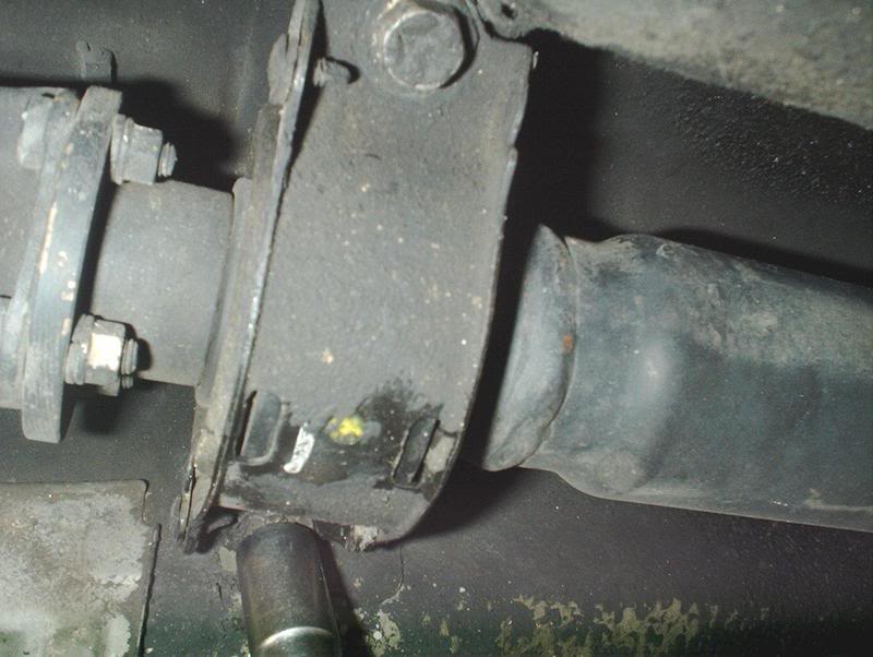
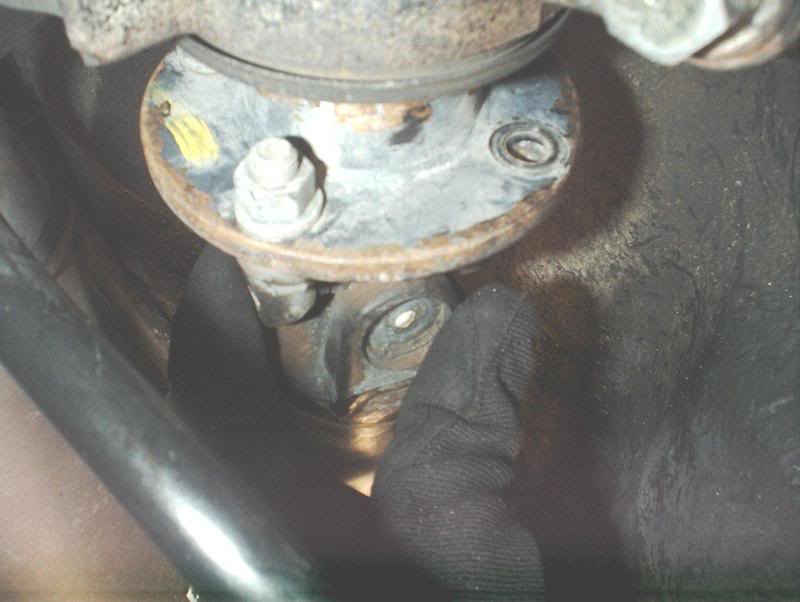
Next, use a 17mm socket to remove the center bearing mounting brackets. There are two bolts on them.
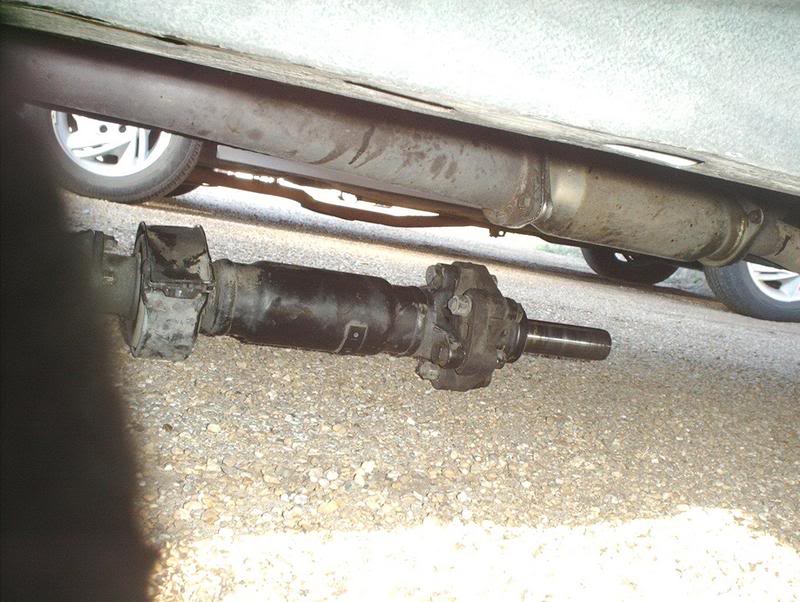
After that I used my hammer to knock the driveshaft loose from the differential. I couldn't budge it with my hands.
Driveshaft.
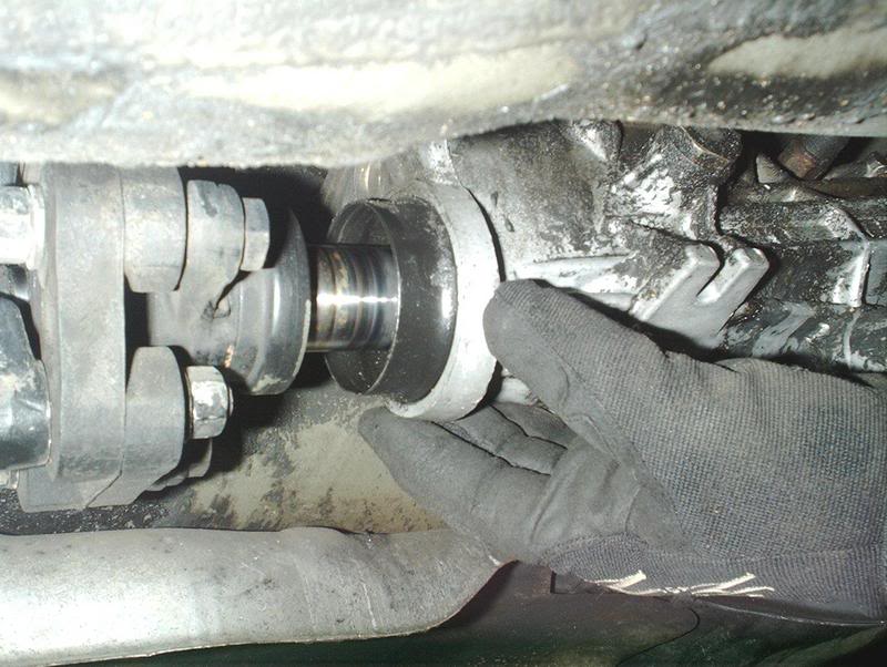
Use your hands to twist and pull the driveshaft from the transmission.
Done!
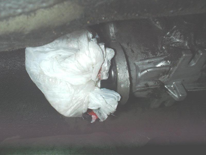
Stash something in the end of the tranny to keep any remaining fluid from dripping out.
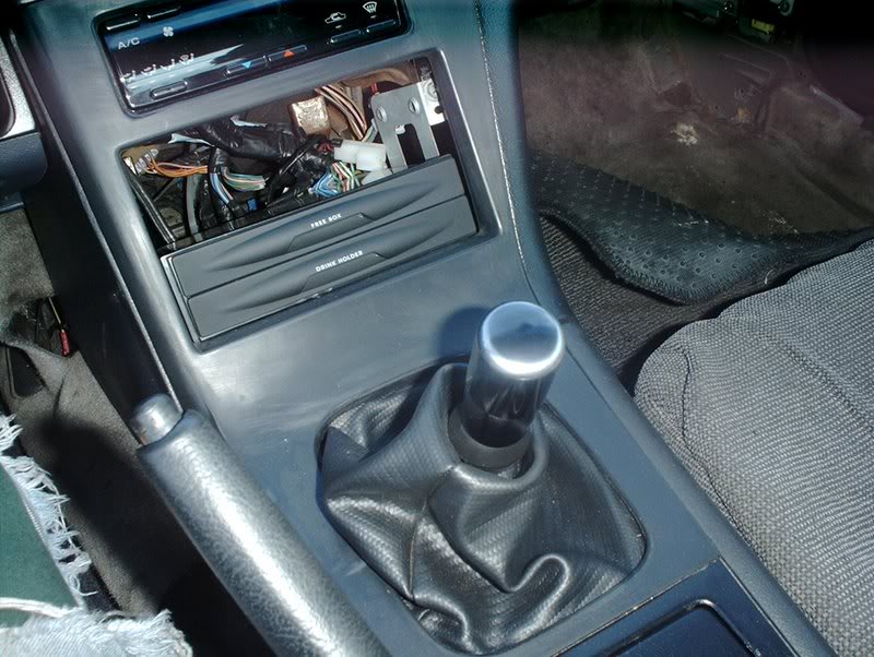
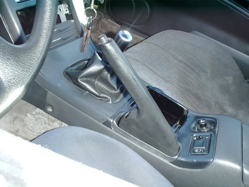
Now for the shifter removal.
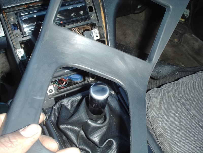
Remove the trim plate and center console.
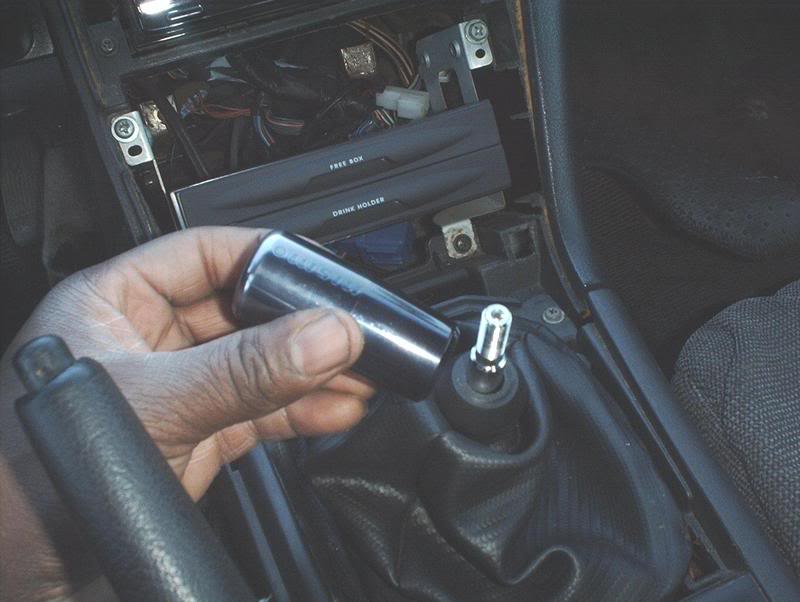
Remove your shift ****.
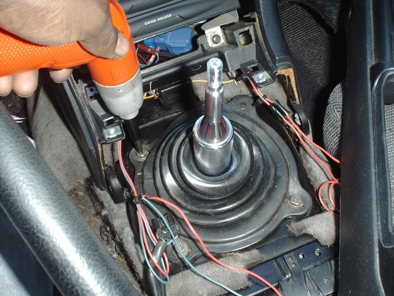
Use a phillipshead screwdriver to remove the four bolts on the shift lever rubber boot.
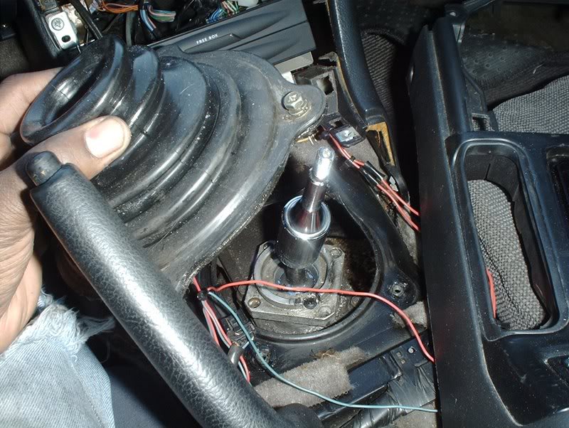
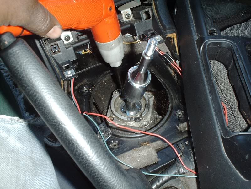
Two bolts here.
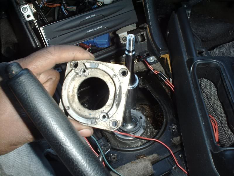
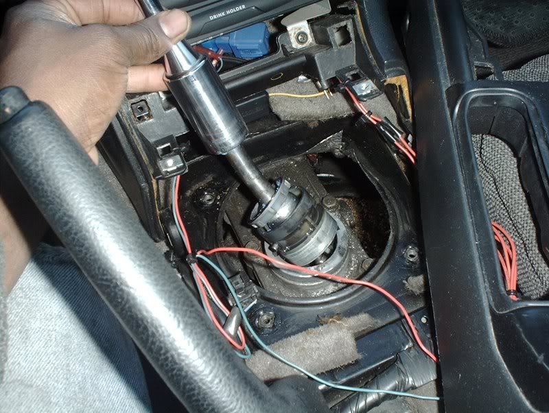
Now you can pull the shifter out. I'm certain again that someone has messed up this car in the past because there was no snap rings on my shifter that needed to be removed which was quite odd.
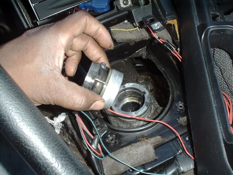
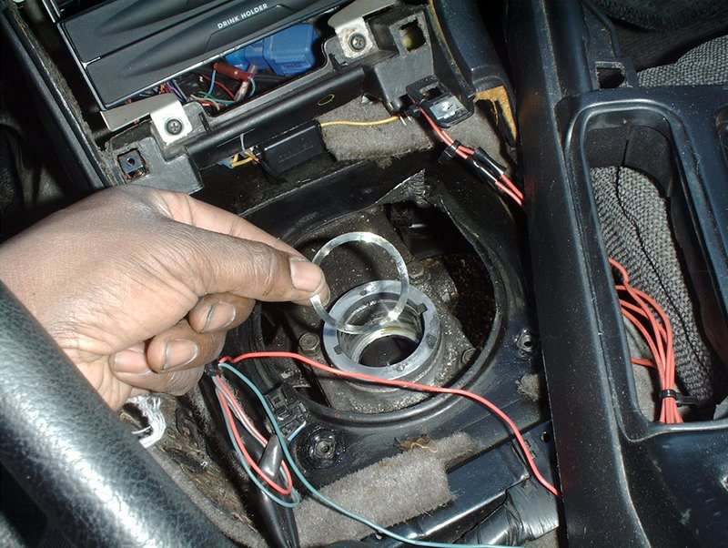
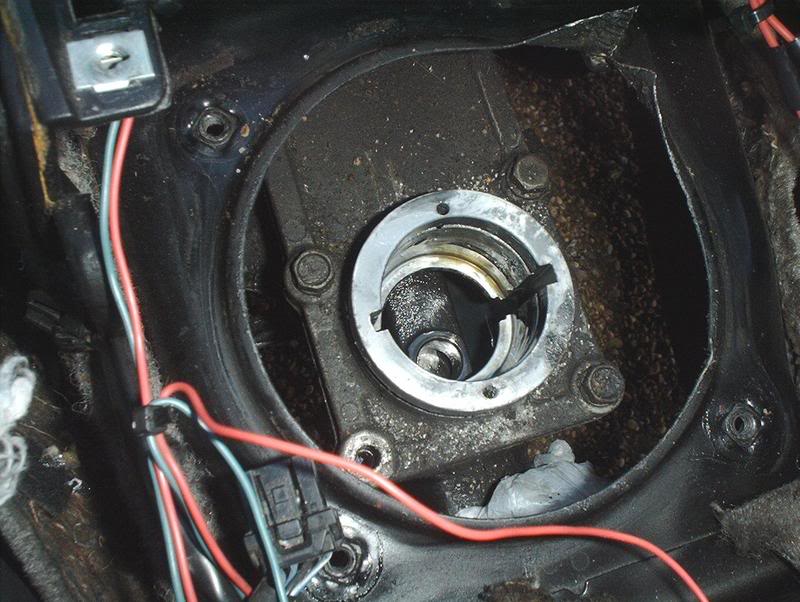
Finished with the shifter removal.
The driveshaft. To remove it you need a 14mm socket or wrench.
I ran into a problem here. I had a 14mm socket but it would not fit flush against the shaft because of its shape. I couldn't get the socket on either side of the driveshaft bolts so I used a 14mm wrench which I could get to sit flush and hit the end of the wrench with my 3lb. hammer(Mjollnir) to bust the nuts loose on the driveshaft bolts.
After you get each nut loose on the driveshaft, you need to go to the inside of the car and let the ebrake down...
so you can spin the driveshaft with your hands which will allow you to move the next driveshaft bolt/nut into position for removal. Let the ebrake back up so the shaft won't spin on you and keep going until you remove all four bolts/nuts.
Next, use a 17mm socket to remove the center bearing mounting brackets. There are two bolts on them.
After that I used my hammer to knock the driveshaft loose from the differential. I couldn't budge it with my hands.
Driveshaft.
Use your hands to twist and pull the driveshaft from the transmission.
Done!
Stash something in the end of the tranny to keep any remaining fluid from dripping out.
Now for the shifter removal.
Remove the trim plate and center console.
Remove your shift ****.
Use a phillipshead screwdriver to remove the four bolts on the shift lever rubber boot.
Two bolts here.
Now you can pull the shifter out. I'm certain again that someone has messed up this car in the past because there was no snap rings on my shifter that needed to be removed which was quite odd.
Finished with the shifter removal.
Last edited by positron; 09-30-2008 at 01:08 AM.
12-16-2007, 10:02 PM
#4
Contributing Member
Thread Starter
Join Date: Sep 2002
Location: Starkville, MS.
Posts: 1,192
Now I'm going to remove the grounds.
I started with the battery cable grounded to the engine. 10mm socket.
10mm socket here. Not sure where this ground is coming from?
10mm or a phillipshead screwdriver for the shock tower.
10mm wrench for the alternator ground.
Alternator grounds.
10mm for the starter ground.
Use a phillipshead screwdriver to remove this ground from the engine to the firewall.
Battery tray.
This is another ground on the rear of the engine near the back of the exhaust manifold.
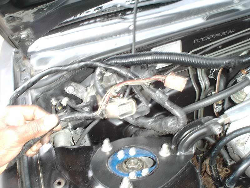
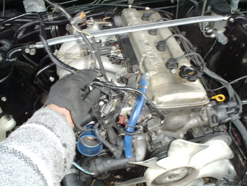
After that I moved on to the engine harness itself.
I started by disconneting all the plugs of the upper engine harness in the engine bay.
Two plugs near the battery tray for light control I believe.
Done!
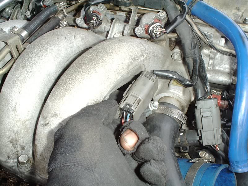
Not sure what this plug is for?
Or this one?
Coolant temp sensor and coolant temp guage sender.
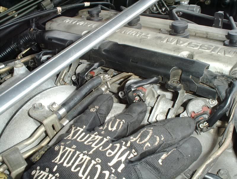
The four fuel injector harnesses.
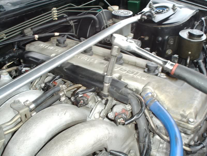
You need a 10mm socket to remove two bolts on this cover before you can get the injector harnesses off.
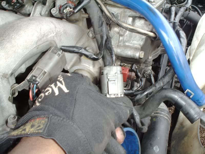
Distributor.
MAF.
Powersteering pump.
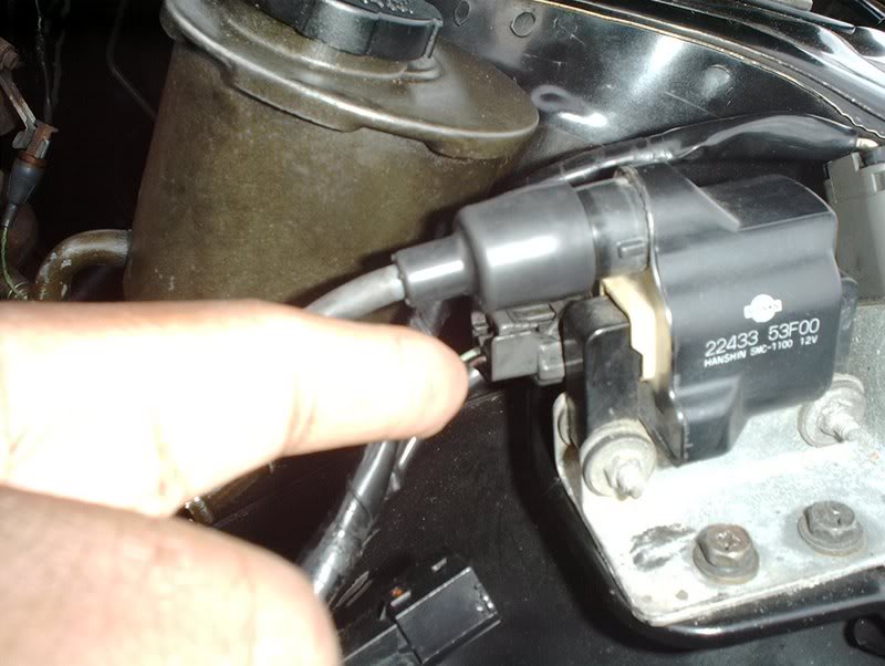
The ignition coil has two harnesses, this one...
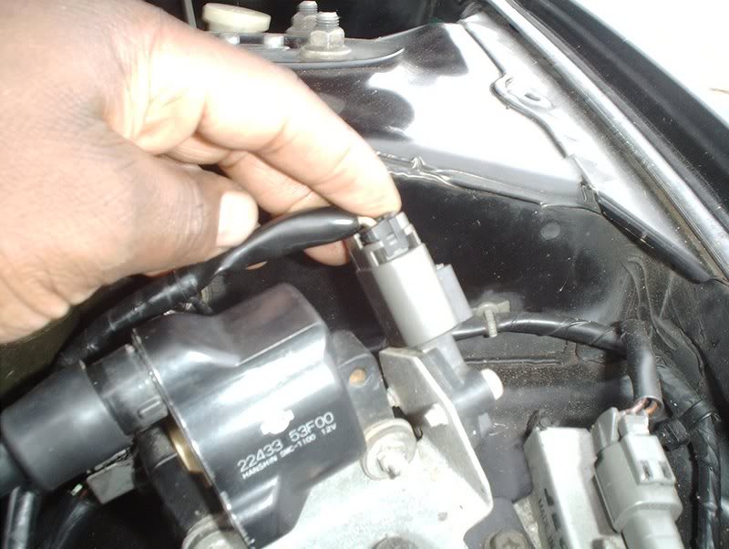
and this one. You'll also have to remove the ignition coil, two 10mm bolts take it right off...
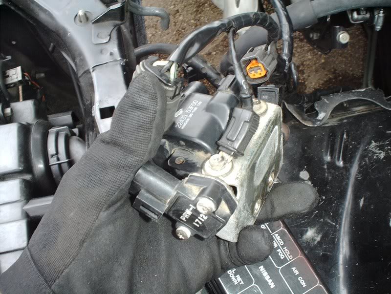
so that you can remove the ground on it. Go ahead and disconnect the spark plug wire while you're at it.
The rear of the valve cover.
The O2 sensor.
Done!
Now to disconnect the harness from the ECU and pull it through the firewall.
I started with the battery cable grounded to the engine. 10mm socket.
10mm socket here. Not sure where this ground is coming from?
10mm or a phillipshead screwdriver for the shock tower.
10mm wrench for the alternator ground.
Alternator grounds.
10mm for the starter ground.
Use a phillipshead screwdriver to remove this ground from the engine to the firewall.
Battery tray.
This is another ground on the rear of the engine near the back of the exhaust manifold.
After that I moved on to the engine harness itself.
I started by disconneting all the plugs of the upper engine harness in the engine bay.
Two plugs near the battery tray for light control I believe.
Done!
Not sure what this plug is for?
Or this one?
Coolant temp sensor and coolant temp guage sender.
The four fuel injector harnesses.
You need a 10mm socket to remove two bolts on this cover before you can get the injector harnesses off.
Distributor.
MAF.
Powersteering pump.
The ignition coil has two harnesses, this one...
and this one. You'll also have to remove the ignition coil, two 10mm bolts take it right off...
so that you can remove the ground on it. Go ahead and disconnect the spark plug wire while you're at it.
The rear of the valve cover.
The O2 sensor.
Done!
Now to disconnect the harness from the ECU and pull it through the firewall.
Last edited by positron; 12-17-2007 at 02:00 AM.
12-16-2007, 10:03 PM
#5
Contributing Member
Thread Starter
Join Date: Sep 2002
Location: Starkville, MS.
Posts: 1,192
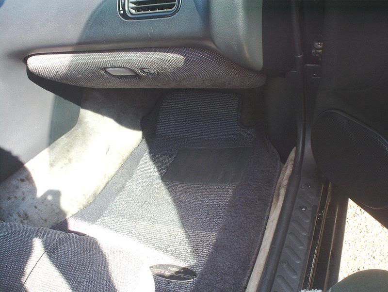
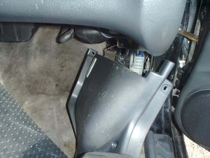
You need to remove the glovebox and kick panel to get to the ECU and the wiring harness.
Use a phillipshead screwdriver to remove the two screws on the glovebox mounting tabs.
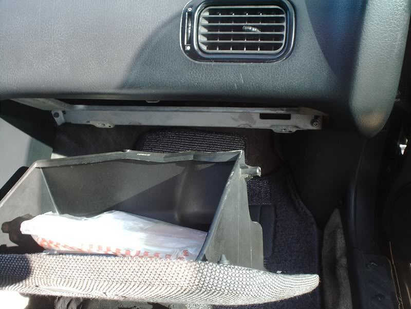
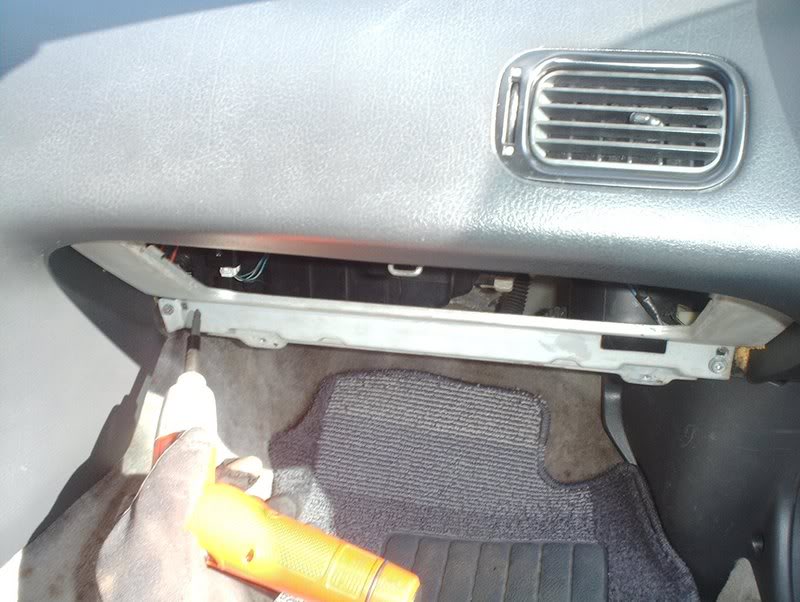
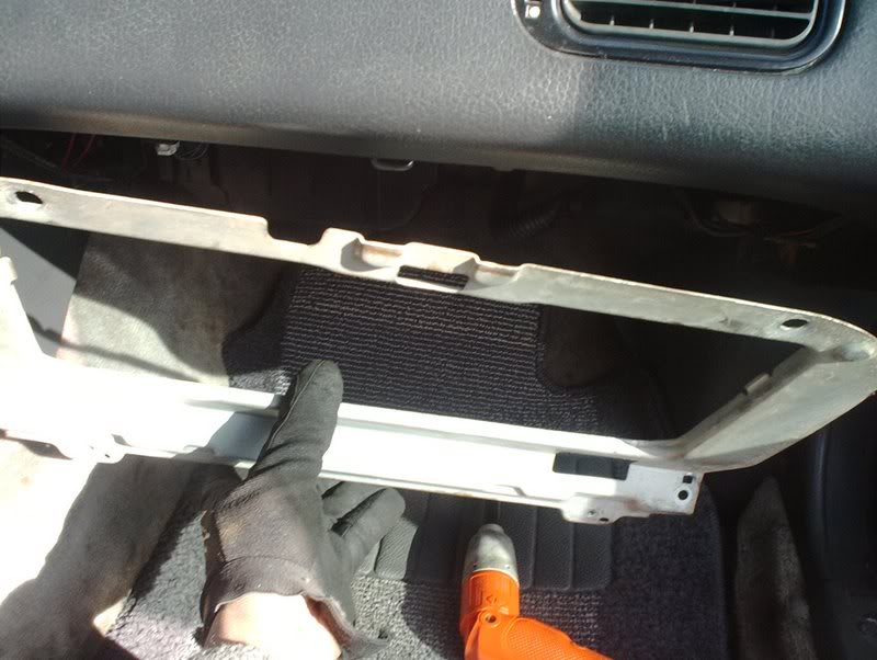
Remove the four bolts holding the glovebox reinforcement.
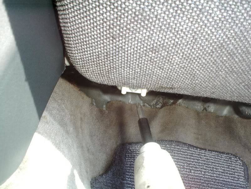
Next you need to remove the clips and bolts holding the kick panel on.
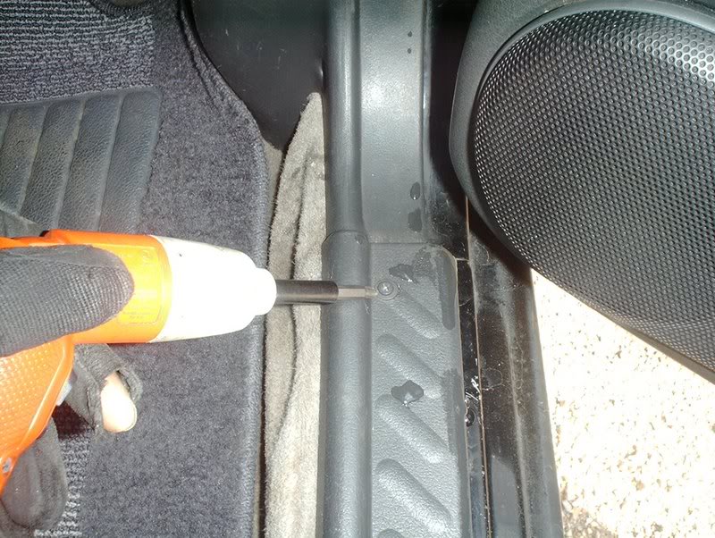
Rocker panel.
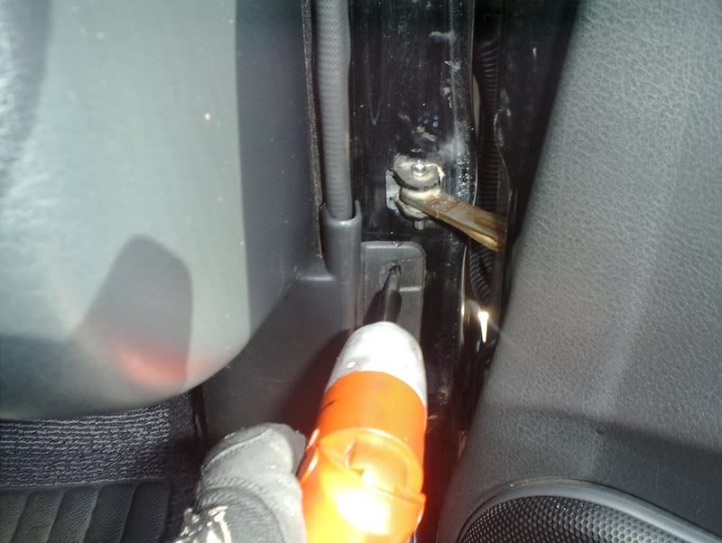
Door jam.
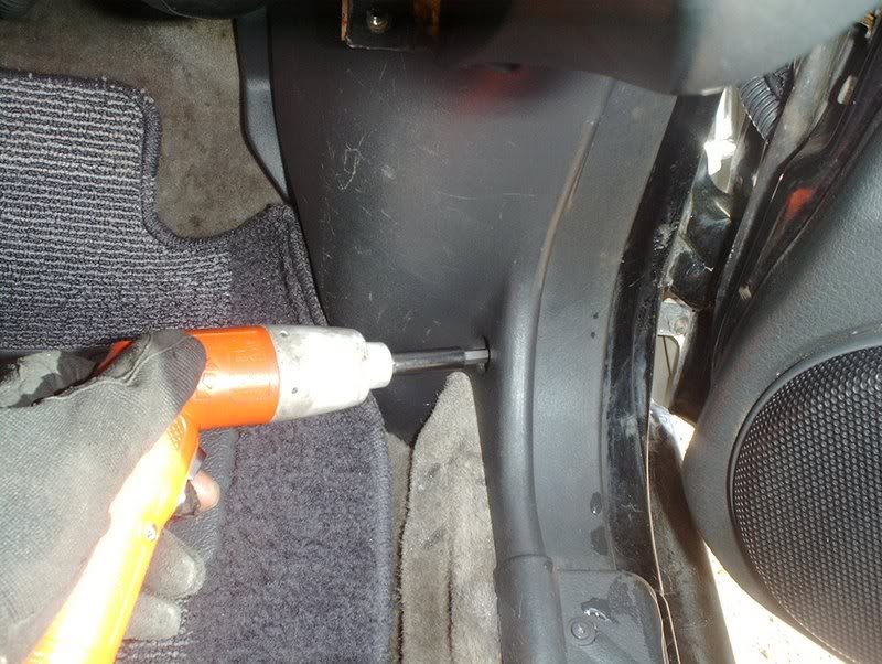
Lower kick panel.
Upper kick panel near the kick panel light.
Done, but don't yank it out...
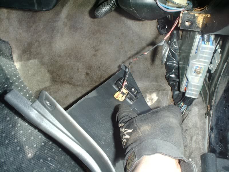
because you have to disconnect the harness for the kick panel light.
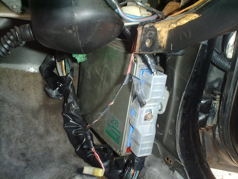
ECU and wiring harness.
Use a phillipshead screwdriver to remove the two bolts holding the ECU to the chassis. This is the lower bolt...
and this is the upper bolt.
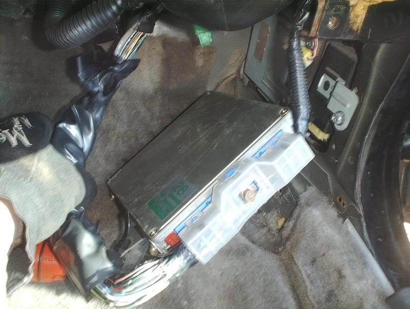
Done!
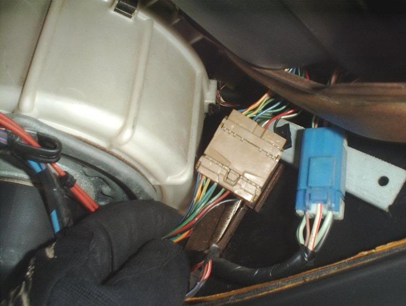
Disconnect this brown harness.
Use a 10mm socket to remove the bolt holding the wiring harness to the ECU.
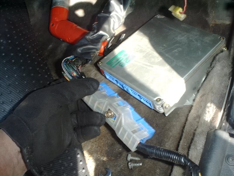
Done!
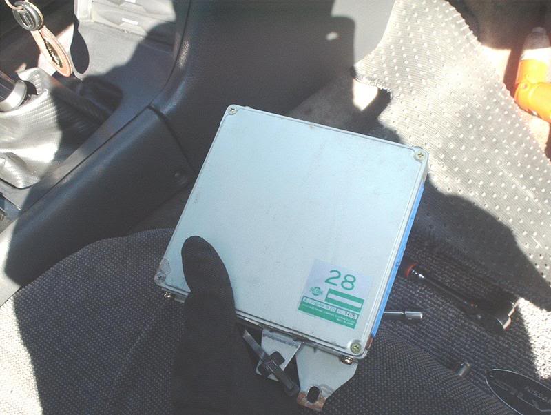
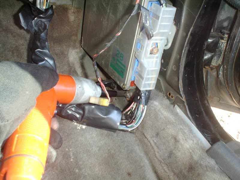
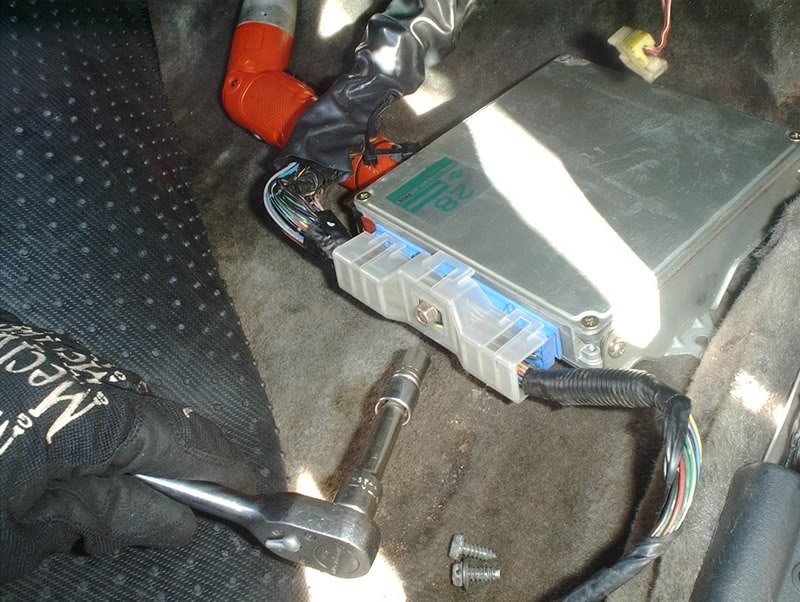
ECU
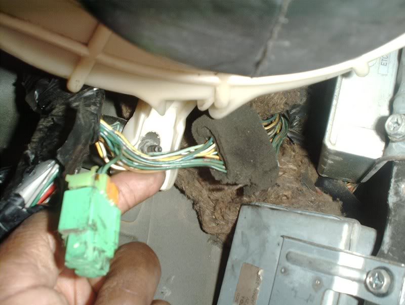
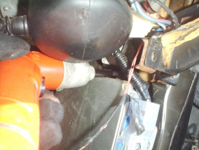
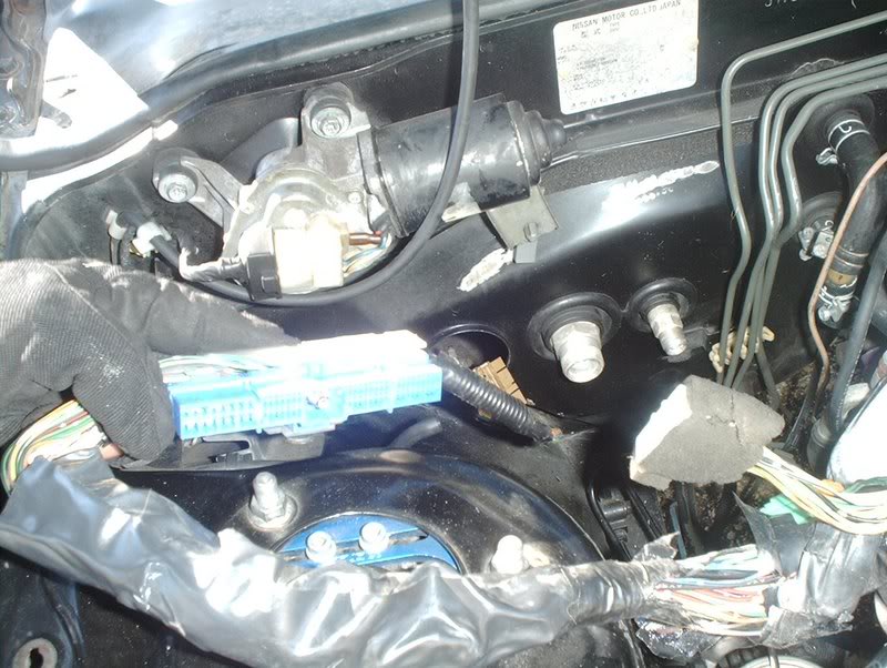
There is another harness that needs to be unplugged here.
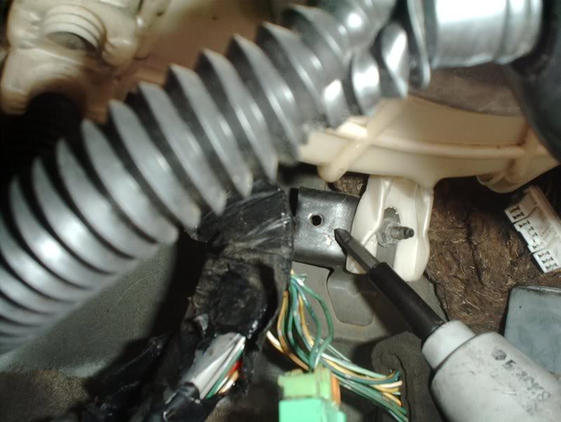
There is a fastener on the wiring harness that holds it to the chassis here...remove it.
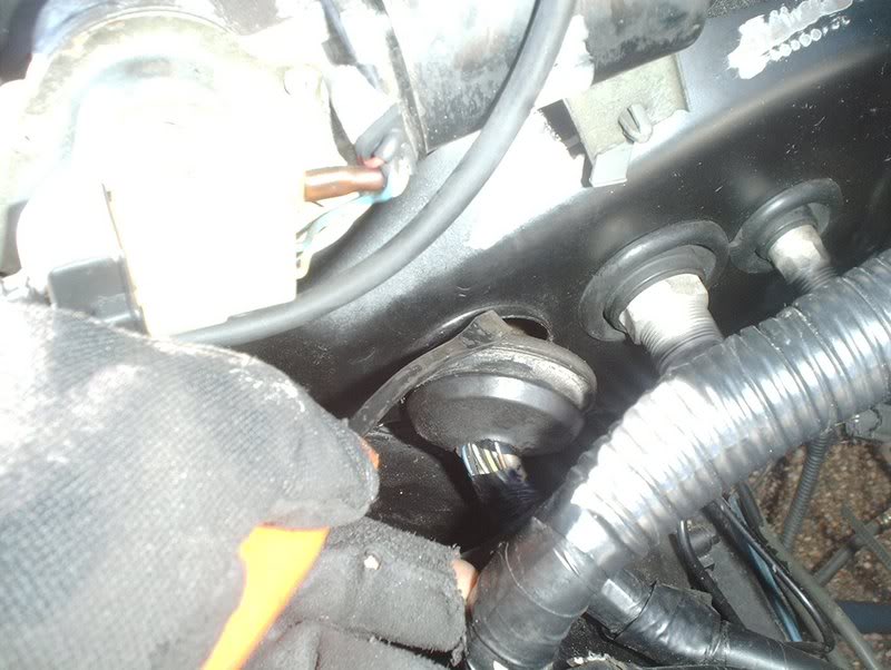
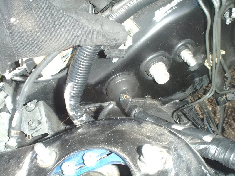
Use a prybar to remove the rubber stopper on the firewall.
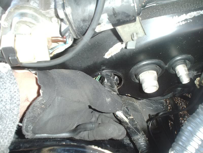
Slowly start pulling the wiring harness through the hole in the firewall.
You may have to go inside and work it through but eventually it comes out.
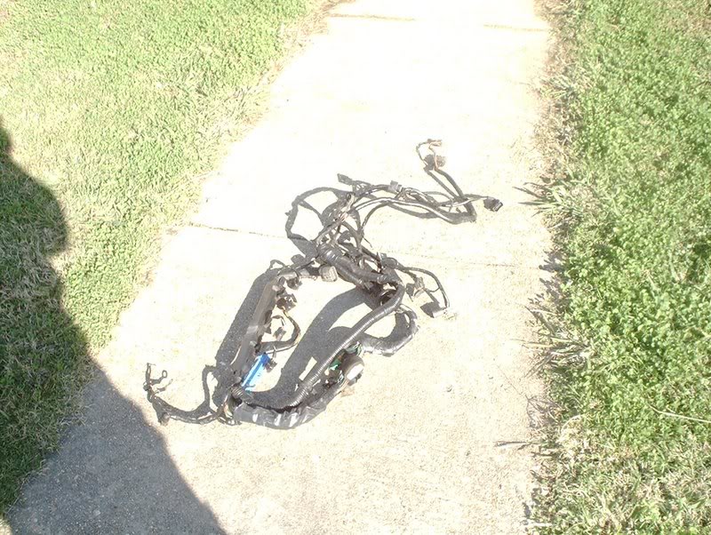
Done! Upper engine harness. If you plan to have the wiring done through a wiring service you will need your SR, CA, RB, etc. wiring harness and the KA upper engine wiring harness to send out to them.
Last edited by positron; 09-30-2008 at 01:09 AM.
12-16-2007, 10:04 PM
#6
Contributing Member
Thread Starter
Join Date: Sep 2002
Location: Starkville, MS.
Posts: 1,192
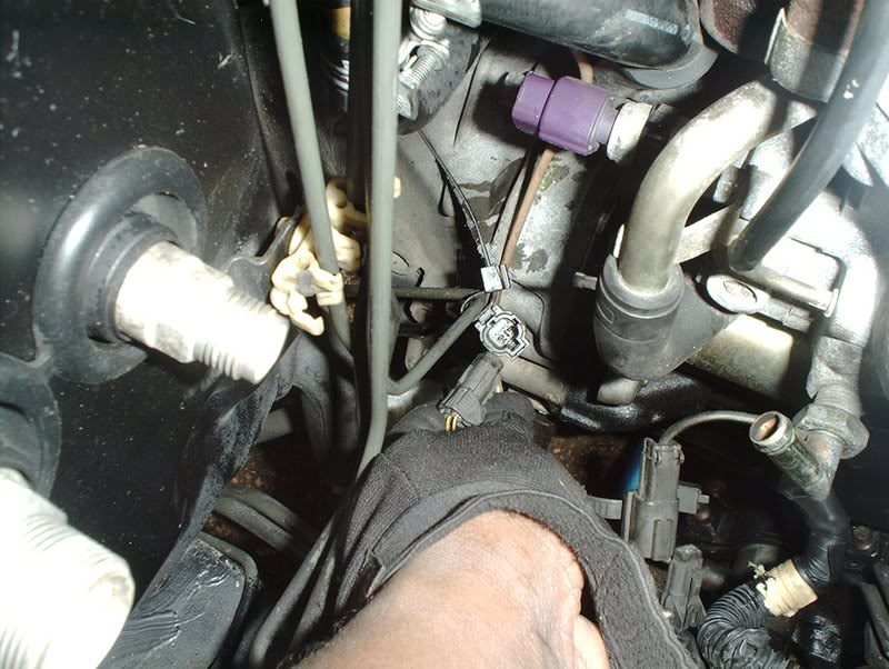
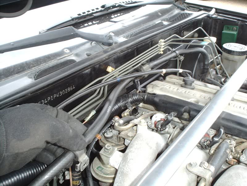
After that I checked the engine bay for any other things connected to the engine, mainly the lower engine harness for plugs still connected to the car.
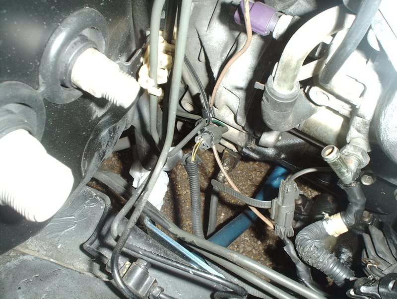
These two.
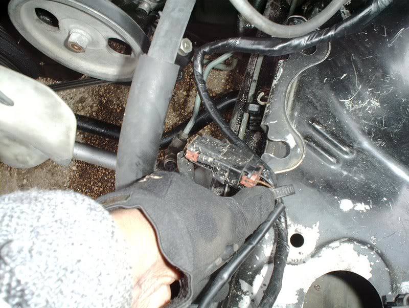
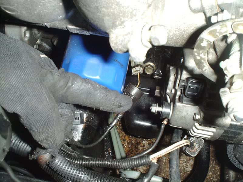
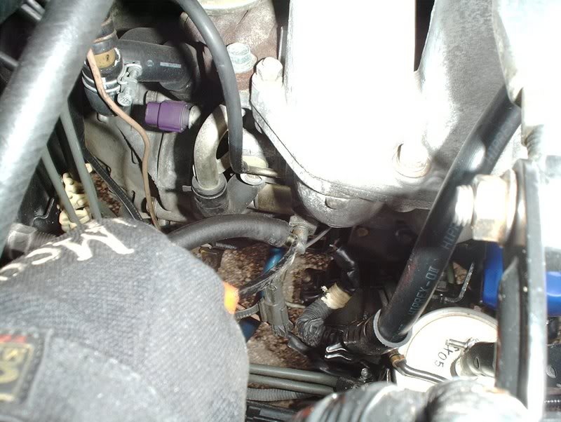
This one was from the starter.
Not sure about this one.
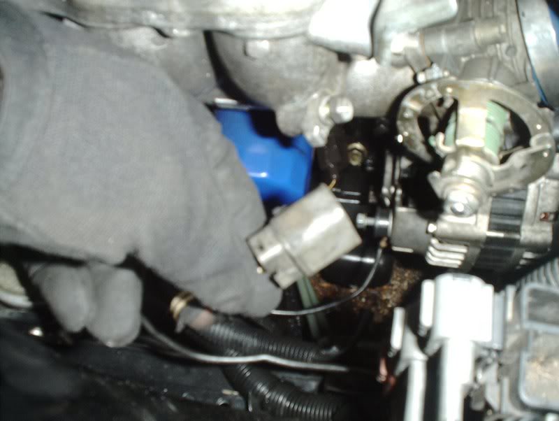
Alternator harness.
Oil pressure sender.
I'm gonna be glad to get rid of this oil leak. Front main seal went out so no more autocrossing for me.
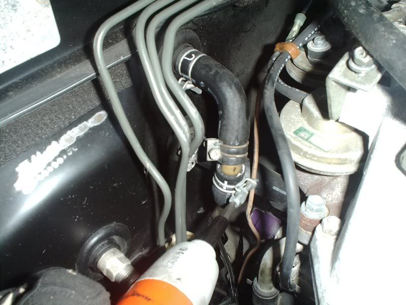
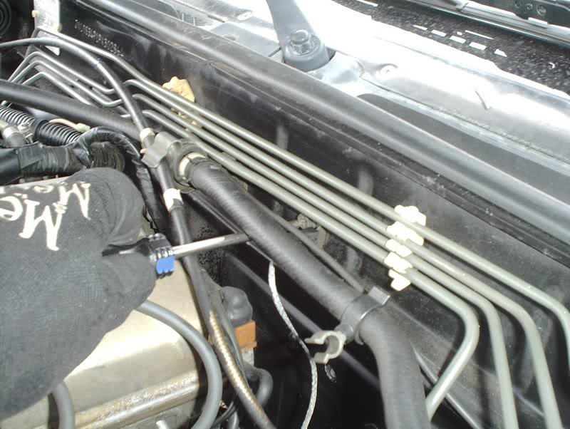
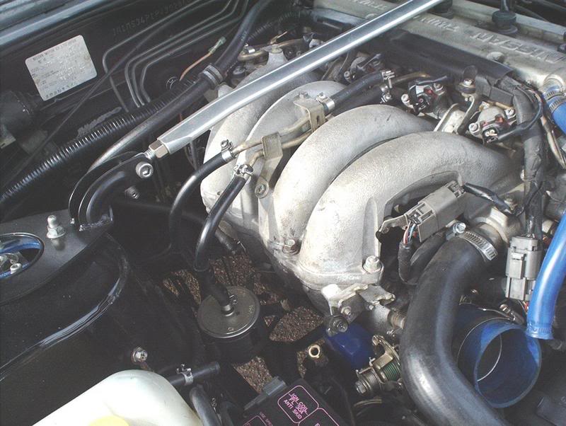
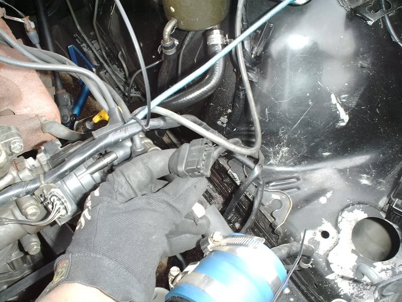
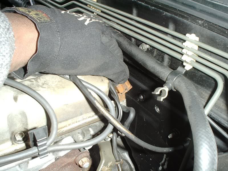
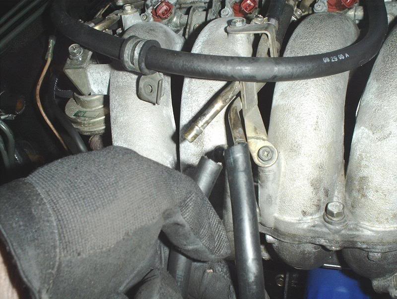
I also removed the heater hoses from the rear of the engine going to the firewall. There are two of them.
The fuel filter hoses need to be removed also.
Done!
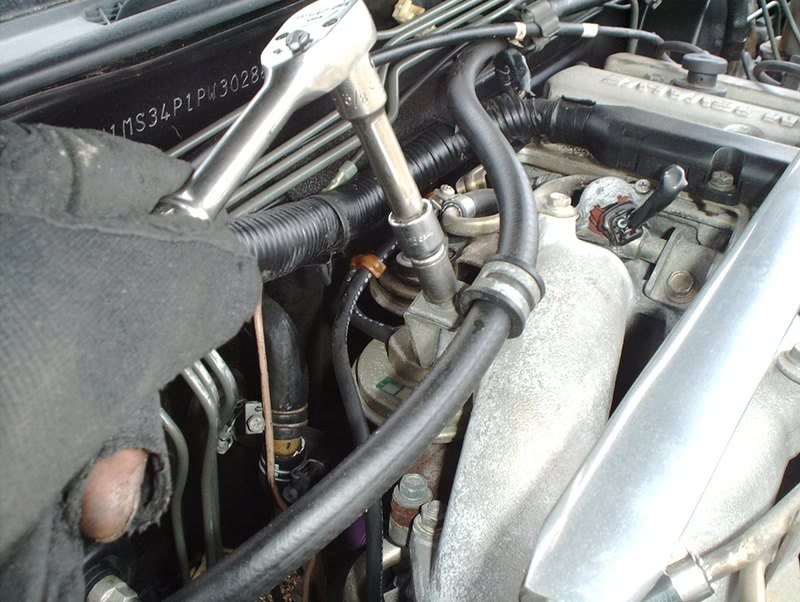
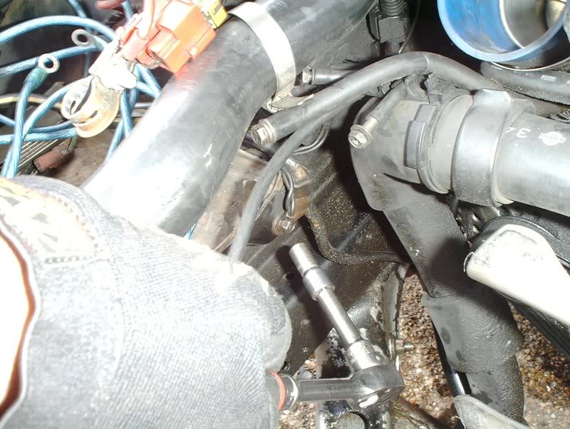
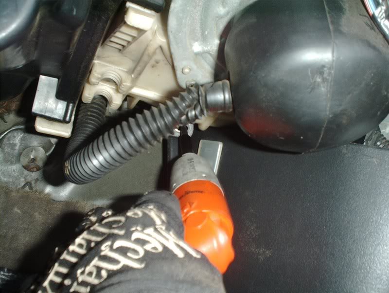
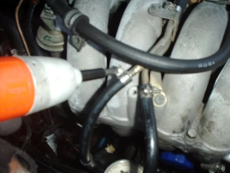
The brake booster hose needs to be disconnected from the engine. Use a 10mm socket to remove this bracket.
Done!
Use a pair of needle nose pliers to remove the end of the brake booster hose from the engine here.
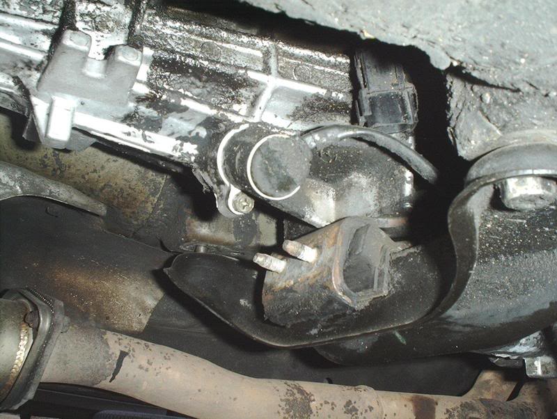
Finally, I removed the motor/transmission mount bolts.
You need a 19mm socket to remove the four transmission crossmember bolts. My car only had 3 crossmember bolts on it....WTF!!!
You need a 15mm socket to remove the left and right motor mount nuts, one under the exhaust manifold and the other located under the intake manifold near the oil filter.
From this point the engine is ready to be chained and hoisted out of the engine bay. I will update this thread with pics when I get a hoist and pull the motor.
These two.
This one was from the starter.
Not sure about this one.
Alternator harness.
Oil pressure sender.
I'm gonna be glad to get rid of this oil leak. Front main seal went out so no more autocrossing for me.
I also removed the heater hoses from the rear of the engine going to the firewall. There are two of them.
The fuel filter hoses need to be removed also.
Done!
The brake booster hose needs to be disconnected from the engine. Use a 10mm socket to remove this bracket.
Done!
Use a pair of needle nose pliers to remove the end of the brake booster hose from the engine here.
Finally, I removed the motor/transmission mount bolts.
You need a 19mm socket to remove the four transmission crossmember bolts. My car only had 3 crossmember bolts on it....WTF!!!
You need a 15mm socket to remove the left and right motor mount nuts, one under the exhaust manifold and the other located under the intake manifold near the oil filter.
From this point the engine is ready to be chained and hoisted out of the engine bay. I will update this thread with pics when I get a hoist and pull the motor.
Last edited by positron; 12-17-2007 at 02:34 AM.


 12-31-2007, 03:31 PM
#14
Contributing Member
Thread Starter
Join Date: Sep 2002
Location: Starkville, MS.
Posts: 1,192
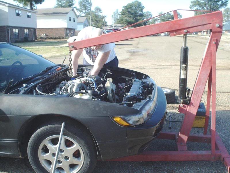
Update!!!
I got a engine hoist and pulled my KA yesterday. There were only a few things that I needed to do before pulling it but it went very smoothly. I bought a 5ft. chain and two links from Lowes and we were ready to get to it.

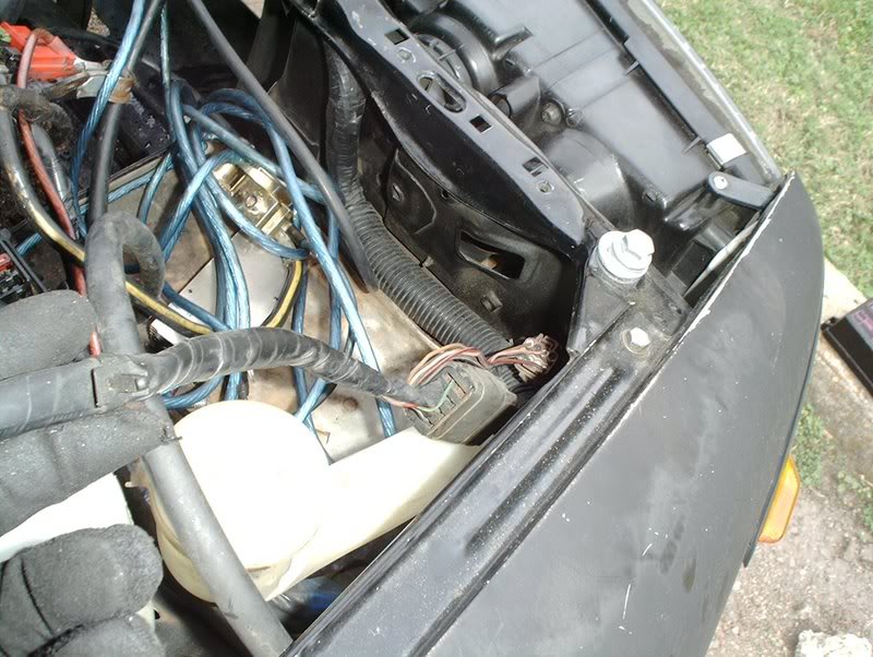
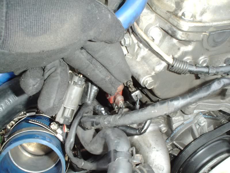
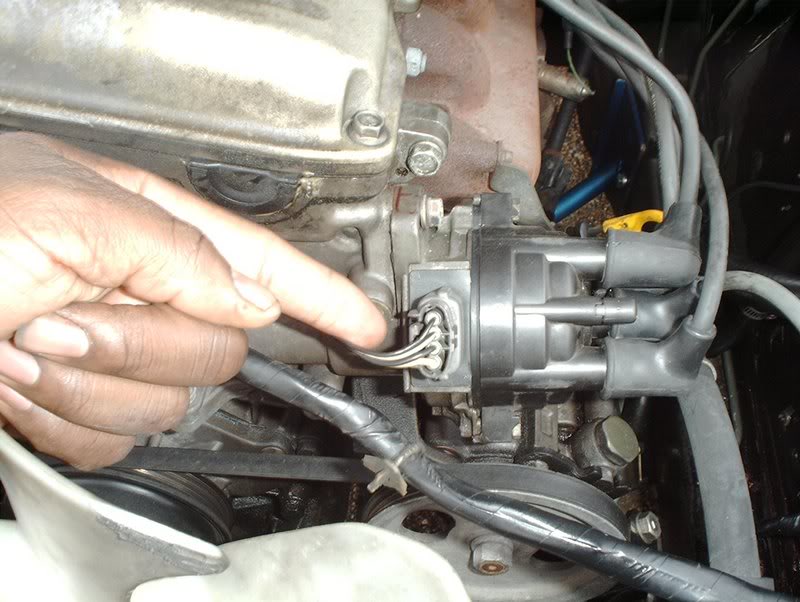
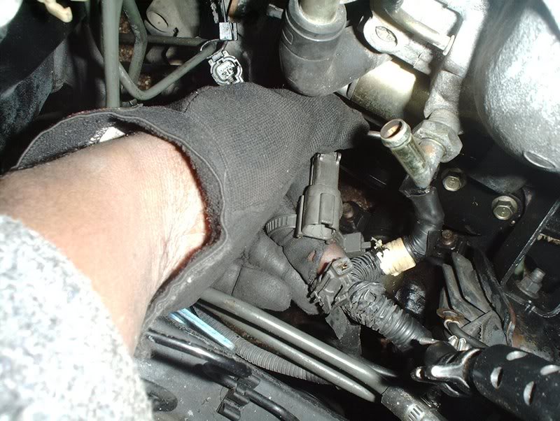
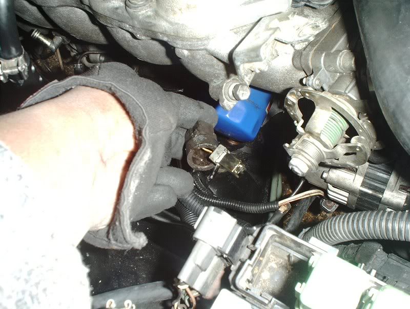
First off, this harness which I couldn't identify before turns out to be the speed sensor harness.
The speed sensor which you will need to remove with a 10mm wrench and unscrew so you can swap it to the SR. After that, I only had to remove the bolts on the header connecting it to the exhaust manifold and the cat.
Remove the hood latch, four bolts with a 12mm socket.
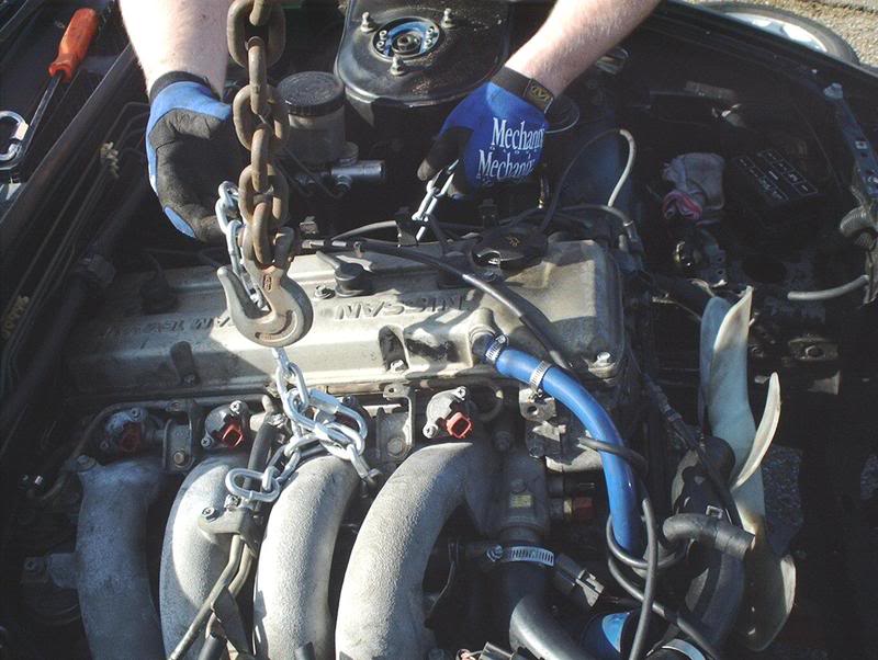
Chain the engine up good, we ran a chain through the intake and exhaust runners...
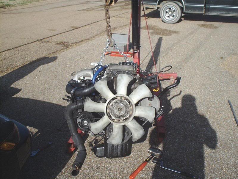
and pull her out slowly. Be careful of the firewall clearance so go slowly and when you get the block clear of the bay have someone get into the bay and pick up on the transmission which is light because the hoist is supporting all the weight. You can then pull it completely out and you are done!
First off, this harness which I couldn't identify before turns out to be the speed sensor harness.
The speed sensor which you will need to remove with a 10mm wrench and unscrew so you can swap it to the SR. After that, I only had to remove the bolts on the header connecting it to the exhaust manifold and the cat.
Remove the hood latch, four bolts with a 12mm socket.
Chain the engine up good, we ran a chain through the intake and exhaust runners...
and pull her out slowly. Be careful of the firewall clearance so go slowly and when you get the block clear of the bay have someone get into the bay and pick up on the transmission which is light because the hoist is supporting all the weight. You can then pull it completely out and you are done!
Last edited by positron; 01-01-2008 at 11:40 AM.


