
S13 Digital Climate Control.

Thread Starter
Registered User
Joined: Jan 2006
Posts: 400
From: Canada
Here is a new goodie for my s13 yummy i love this.
I purchased it but now i need to know what sensors im missing the only one i know what the hell it is is the Round thing which is the sunloader sensor and the other one which looks like an intake of somesort? I looked around google for info but im lost otherwise here are some pics. I know i need a few other things but unsure which ones. They can be interchanged with the ones from an early 90's maxima and therefore i need to know what else i need.


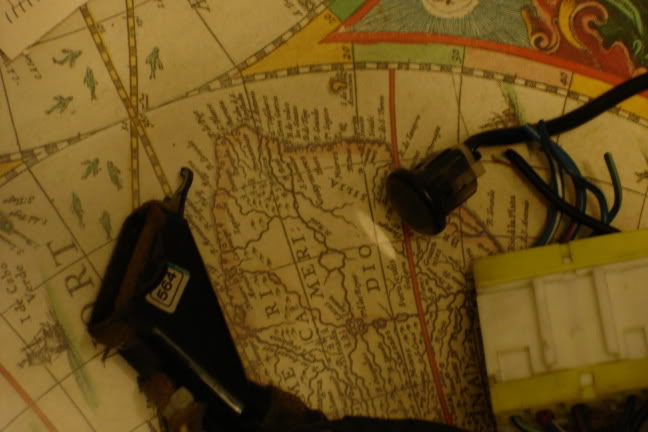
there are some pics thanks in advance.
Oh and does anyone also know how to remove scratches from something like this there is a nice fat scratch covering 1/2 of it on the top end if i could dull it or blend it in would be great. Thanks again.
I purchased it but now i need to know what sensors im missing the only one i know what the hell it is is the Round thing which is the sunloader sensor and the other one which looks like an intake of somesort? I looked around google for info but im lost otherwise here are some pics. I know i need a few other things but unsure which ones. They can be interchanged with the ones from an early 90's maxima and therefore i need to know what else i need.
there are some pics thanks in advance.
Oh and does anyone also know how to remove scratches from something like this there is a nice fat scratch covering 1/2 of it on the top end if i could dull it or blend it in would be great. Thanks again.


Registered User
Joined: May 2004
Posts: 11
From: Melbourne
The intake looking sensor sits behind the centre console panel just under the DIN slot
From SilviaWA Forums
From SilviaWA Forums
Parts Required
Digital control unit, sub-loom wiring (2 plug version). If you intend to make them interchangeable, as I have, you will also need: 2 Pin plug, (2x female, 1x male), and a 5 pin plug, (2x female, 1x male). You could substitute these plugs for common bullet style connectors, (7x female, 14x male). (You need 1 set of males for the loom in the car, and 2 sets of females, 1 for each control unit.) You will also need a short length of wire (20cm) and a common female spade connector.
Tools
Phillips screwdriver, wire strippers, sidecutters, crimping tool and soldering iron/solder.
Converting
Pull off the cover/surround from around the aircon/stereo/gearstick. Remove the 4 screws securing the stereo/storage bin, and remove the unit from the dash. There is no need to disconnect the wiring. (Depending on your wiring) Sit this out of your way.
Remove the 4 screws securing the climate control unit, and the unit will come out by first pushing it into the dash, and pulling it out thru the stereo hole. Disconnect the 3 plugs from the back of this unit, and put it aside.
Reach into the dash, and follow the aircon wiring until you find the plugs at the other end. Disconnect all of these plugs. Remove the blue relay from the bracket on the driver's side. (If the wiring with your digital unit has no relay connected, leave this in place.) You should now find that there is two groups of wires left, with no plugs. (Hard Wired.) There are 5 wires in one, and 2 in the other. Remove some tape from both of these, and cut all 7 wires, at the same distance, ONE AT A TIME. (We didn't disconnect the battery, remember? We don't want to short out any live wires here.)
Now, remove the sub loom from the dash. Placing it alongside the digital loom, you will see that all these 7 wires have the same colour codes, between the two looms.
Colours are: Orange/Blue stripe, Pink, Pink/Blue stripe, Pink/Black stripe, Purple, in group of 5, and Light Green/Black stripe, Dark Green/Yellow stripe in group of 2.
Now, if you don't want interchangeability, simply solder Purple on Sub loom to Purple in main loom, and so on, for all 7 wires.
For interchangeability, attach the plugs mentioned under "Parts" to both control unit sub looms, and to the main loom. Control unit looms both get the "female" side of the plugs, and the "male" goes onto the main loom. The 2 Green wires should be grouped onto the 2 pin plug, with the remaining wires utilising the 5 pin plug. (When attaching plugs, take care to ensure that each colour wire corresponds with its counter-part in the other loom.)
Now, find the constant power (memory) wire for your stereo. (If you have an aftermarket stereo, it is the yellow wire, orange for Pioneer.) Strip back a little bit of the plastic from this wire, and solder the 20cm length of wire you have into this wire. Attach the female spade connector to the other end of this wire. Ensure you cover the soldered joint properly with electrical tape. Now, connect the spade terminal to the single red wire left from the control unit sub loom. If you haven't already done so, connect up the plugs you attached to each loom, and connect the 2 plugs to the back of the digital control unit.
Before putting it all back together, you may like to test it. (NOTE: The auto function will not work without the sensor on the surround connected.)
Putting It Together
Put the control unit back in thru the stereo hole, and move into position. Replace the 4 retaining screws. Fit the stereo head unit back into place and secure with it's 4 screws. (Ensure the wire/plug for the sensor does not get caught in behind the stereo.) Now, attach the sensor plug and the little black tube, and clip the surround back in place, and, job done.......
To swap later, if required, it is now plug'n'play, for those who used the plug method, except you don't need to connect the constant power wire for the analogue unit.
Registered User
Joined: May 2004
Posts: 11
From: Melbourne
it normally friction fits around a bevel on the back of the console insert - as you can see it has foam on it to make a seal with the insert. The console insert (the piece of plastic that goes around the gearstick and up around the din slots) has a grille cut into it, about 1.5cmx2cm above and to the right of the gearstick
its just an ambient sensor so i reckon you could mount it anywhere around that general area
id post pictures but my 180 doesnt have climate control
its just an ambient sensor so i reckon you could mount it anywhere around that general area
id post pictures but my 180 doesnt have climate control

Thread
Thread Starter
Forum
Replies
Last Post
brent240
Private For Sale / Wanted
0
Sep 16, 2005 10:39 PM

