My S13 SR20DET Prep


 09-03-2008, 05:12 PM
#212
Contributing Member
Thread Starter
Join Date: Sep 2002
Location: Starkville, MS.
Posts: 1,192
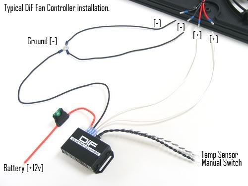
Fan Controller Continued...
I got some wire so I started on the fan wiring finally.
Tools needed:
Wire cutters
14 guage wire
Butt connectors
I had to decide wether to wire the fan motors for high power or low power and I opted for low power because of people saying that the fan motors burn out prematurely on high power.
-------------------------------------------------------------------------------
+12v blue, (-12v black & -12v green) == low speed
+12v yellow, (-12v black & -12v green) == high speed
(+12v blue & +12v yellow), (-12v black & -12v green) == fans don't spin at all!
--------------------------------------------------------------------------------
Low Speed: blue connects to +12v source, black and green connect to ground.
High speed: yellow connects to +12v source, black and green connect to ground.
--------------------------------------------------------------------------------
These elec fans have 4 wires EACH.
2 go to 12V
2 go to GROUND
Low speed requires ONE 12V lead and ONE ground lead...
High Speed requires BOTH 12V active and BOTH Grounds active.
On my 240 and 200sx have the same color's on the fans and the FSM's state the same pattern.
BLUE & GREEN are the two 12V sources
YELLOW & BLACK are the GROUND sources.
BLUE 12V & YELLOW Ground will give LOW speed
BLUE 12V & BLACK Ground will also give LOW speed
GREEN 12V & YELLOW Ground will also give LOW speed
GREEN 12V & BLACK Ground will also give LOW speed
BLUE 12V & GREEN 12V with YELLOW ground & BLACK ground will give HIGH speed....
---------------------------------------------------------------------
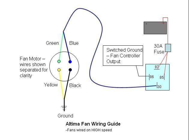
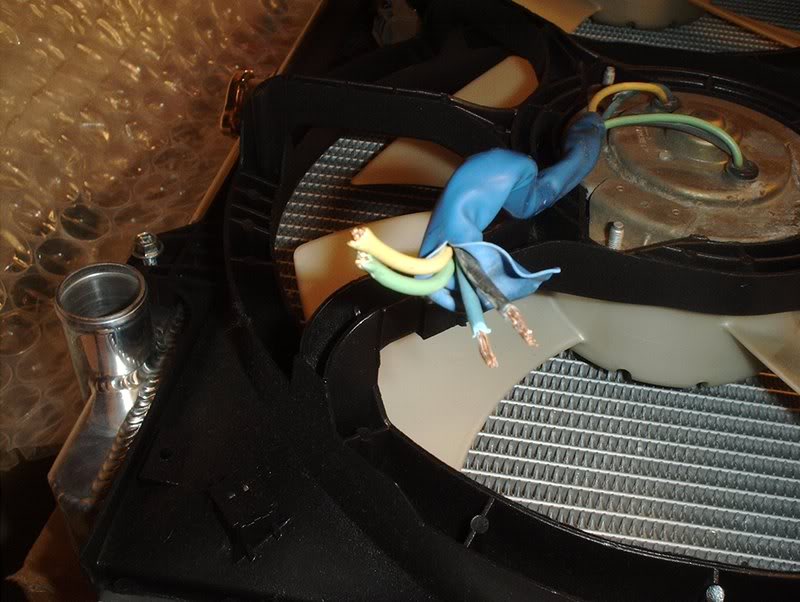
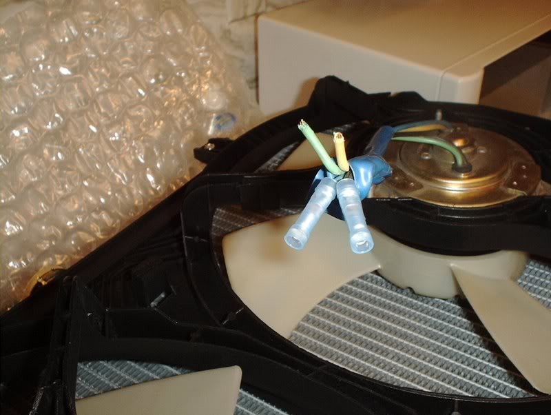
Using the provided diagram, it easily explains that there are four wires on each fan motor.
BLUE-12V power
GREEN-12v power
BLACK-GROUND
YELLOW-GROUND
So if I were wiring them for high power I would use all four wires but since I'm going with low power...I'll only use two. One wire for power and one for ground. There didn't seem to be a question as to which set I used so I chose the blue power and the black ground. The green power and the yellow ground will just be bypassed.
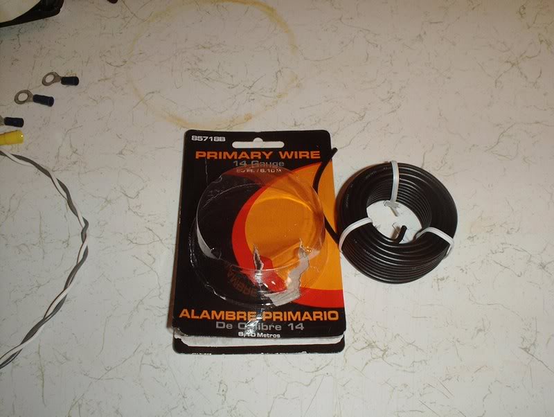
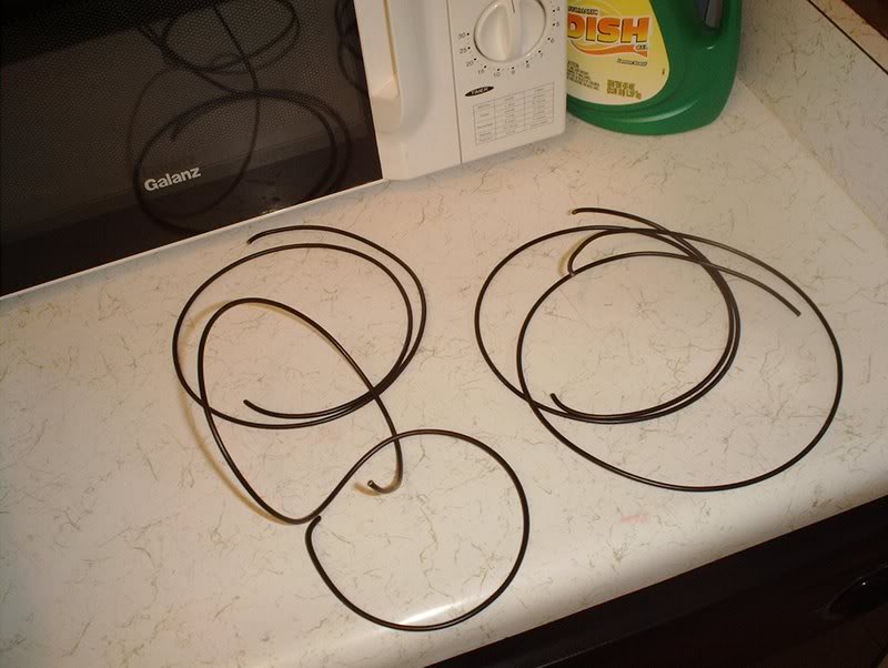
14 gauge wire. It seems to be the same guage as the wire that was provided with the fan controller unit.
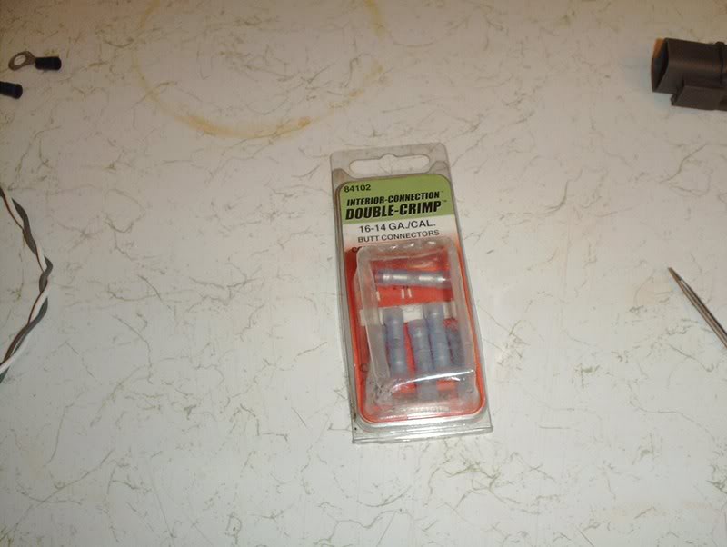
Butt connectors. You'll need these to wire the fan motors.
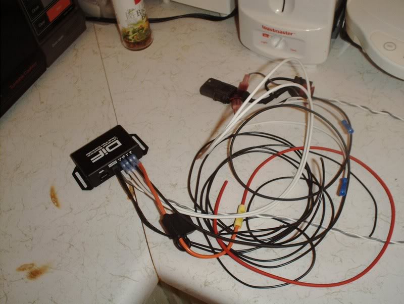
Bird's nest!
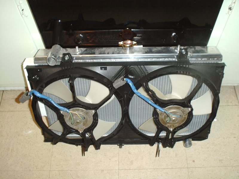
Fan motors.
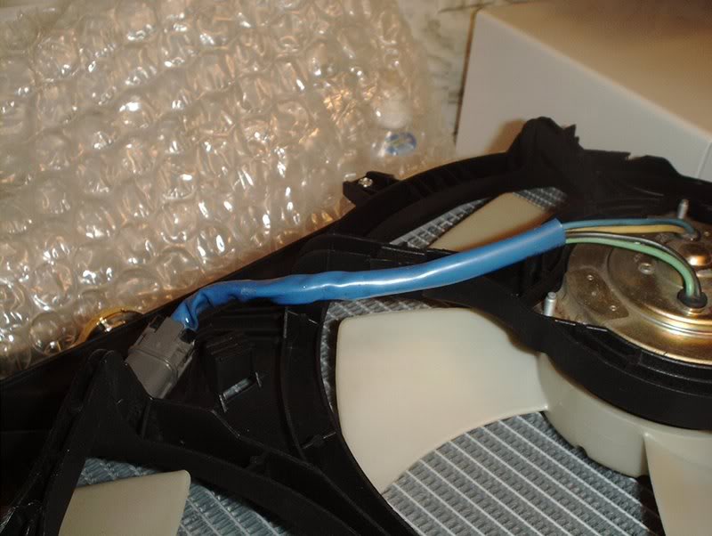
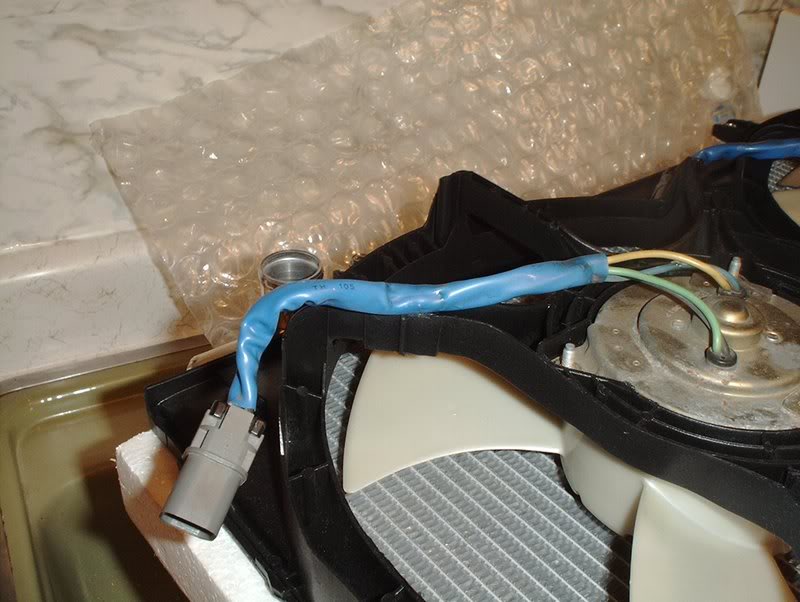
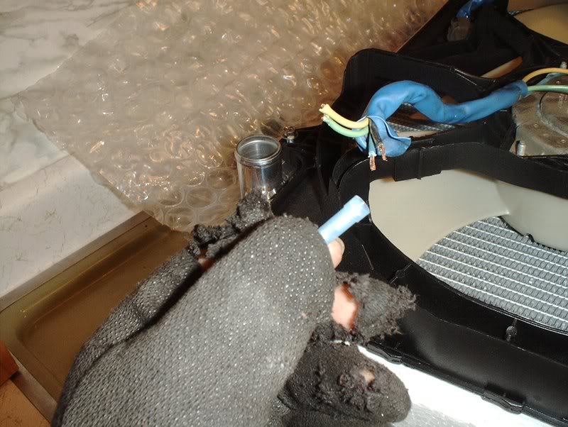
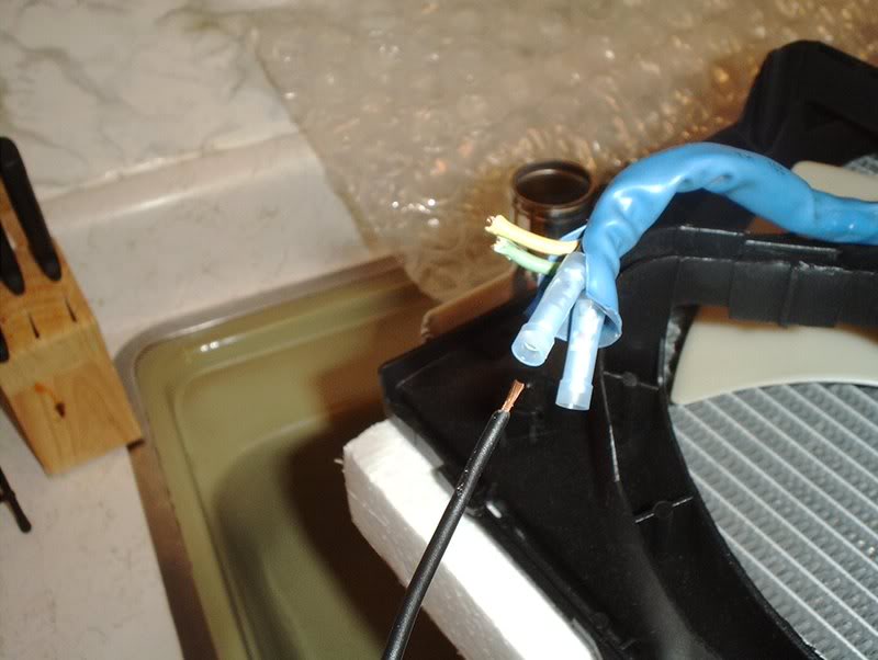
These are the two plugs that will need to be rewired.
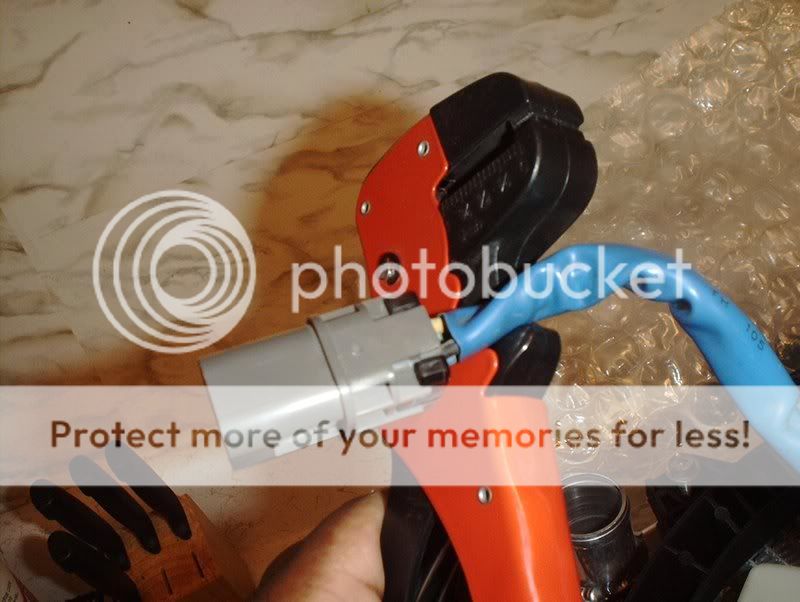
I took a pair of wire cutters and cut the plugs off.
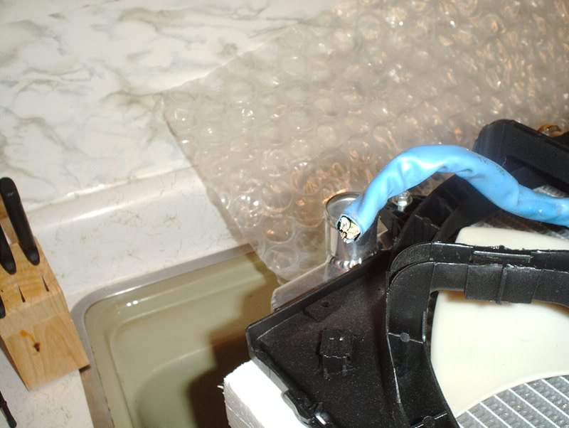
Like so.
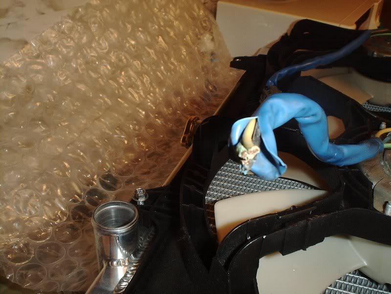
I took a razorblade and cut some of the protective sheath back for some extra work space and bent the other wires out of the way since I'll only be needing the blue and the black. Speaking of those other wires, since I won't be using them should I tape or solder them off anyway? There will be no power running through them as far as I know.
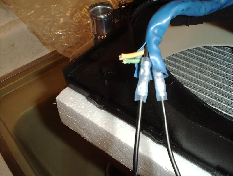
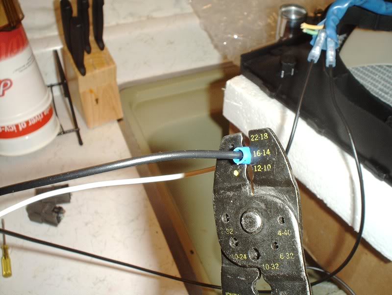
Use the wire cutters to strip the end of the wires.
I started with the power wire first, take a butt connector(16-14) and place the wire in.
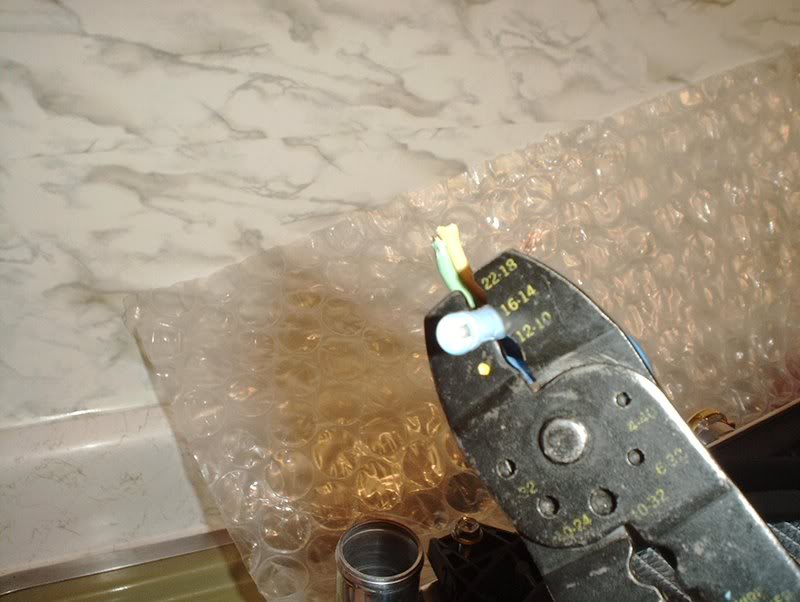
Crimp it to 16-14.
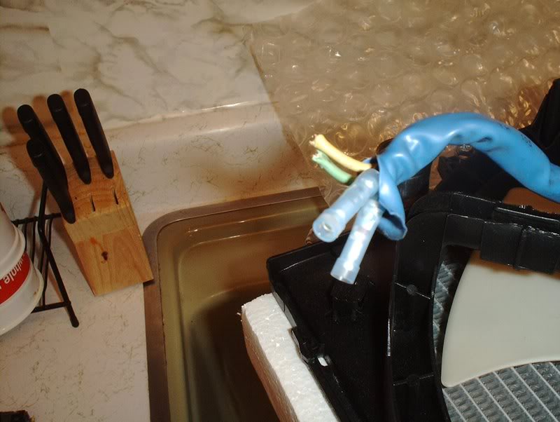
Repeat for the ground wire...
as well as the other fan motor.
I'm not certain how much wire I'm going to need to run for this setup so I just cut about a foot and a half, which is probably way too much, but I can always trim it down after the install. You'll need to cut four wires, two for the power and two for the grounds.
I took the first wire, stripped the end...
and inserted it into the butt connector. Crimp to 16-14. Repeat for the other butt connector.
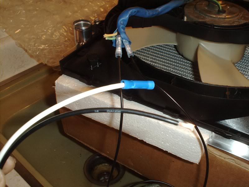
Take the white wire coming from the FAN1 outlet on the fan controller, strip the other end of the EXTRA wire...
insert and crimp to 16-14. Repeat this for the FAN2 white power wire and the other EXTRA wire as well.
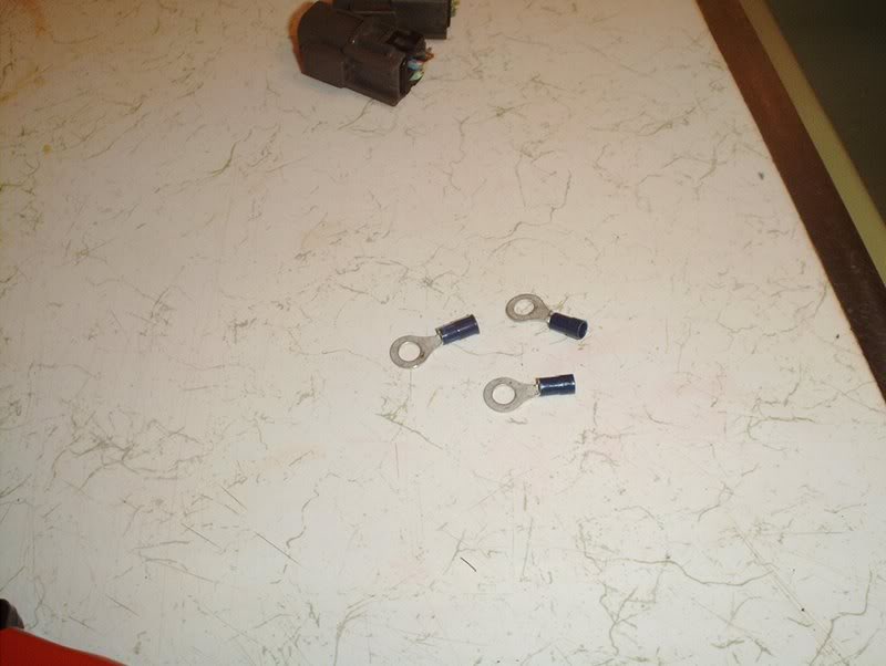
These are the three ring terminals provided for ground that came with the fan controller unit.
The grounds will be wired up like so.
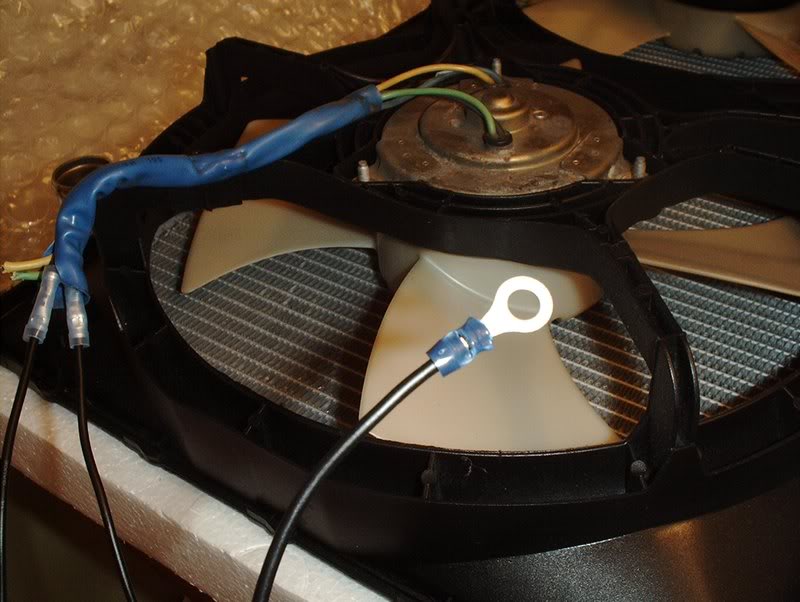
Take one of the EXTRA ground wires, strip it, place the ring terminal on and crimp to 16-14.
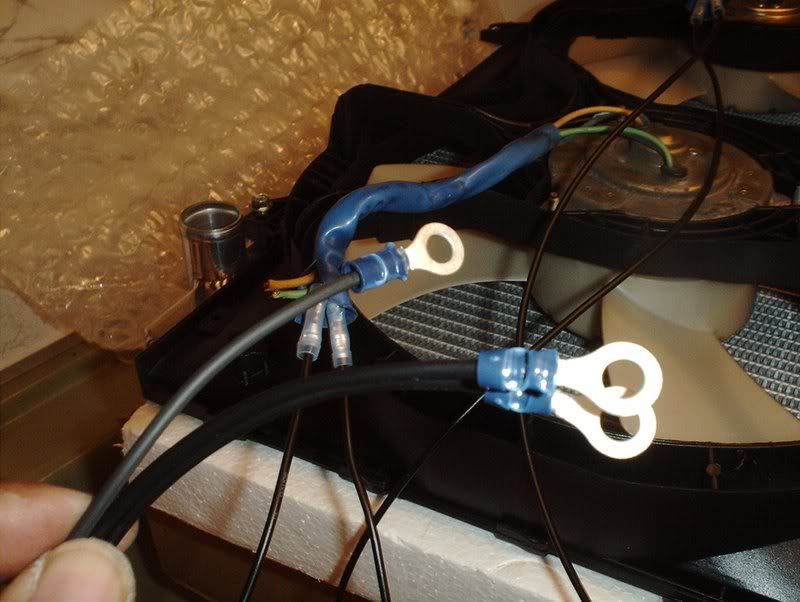
Repeat for the other fan motors EXTRA ground wire. These will go in a ground spot in the engine bay.
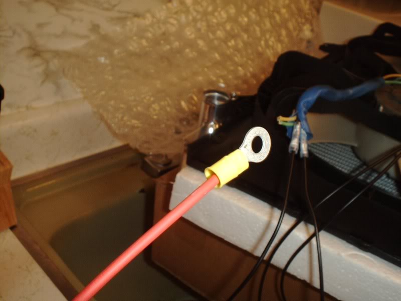
While I was at it, I used the last provided yellow ring terminal for the fan controller unit's power source. Strip, insert and crimp to 16-14. This will be connected directly to the battery and will power the actual DIF fan controller unit which will in turn provide power to the individual fan motors from there...correct?
When I get my battery cables back, I'll post up a test to see if these fans work with this setup.
TO BE CONTINUED...
Tools needed:
Wire cutters
14 guage wire
Butt connectors
I had to decide wether to wire the fan motors for high power or low power and I opted for low power because of people saying that the fan motors burn out prematurely on high power.
-------------------------------------------------------------------------------
+12v blue, (-12v black & -12v green) == low speed
+12v yellow, (-12v black & -12v green) == high speed
(+12v blue & +12v yellow), (-12v black & -12v green) == fans don't spin at all!
--------------------------------------------------------------------------------
Low Speed: blue connects to +12v source, black and green connect to ground.
High speed: yellow connects to +12v source, black and green connect to ground.
--------------------------------------------------------------------------------
These elec fans have 4 wires EACH.
2 go to 12V
2 go to GROUND
Low speed requires ONE 12V lead and ONE ground lead...
High Speed requires BOTH 12V active and BOTH Grounds active.
On my 240 and 200sx have the same color's on the fans and the FSM's state the same pattern.
BLUE & GREEN are the two 12V sources
YELLOW & BLACK are the GROUND sources.
BLUE 12V & YELLOW Ground will give LOW speed
BLUE 12V & BLACK Ground will also give LOW speed
GREEN 12V & YELLOW Ground will also give LOW speed
GREEN 12V & BLACK Ground will also give LOW speed
BLUE 12V & GREEN 12V with YELLOW ground & BLACK ground will give HIGH speed....
---------------------------------------------------------------------
Using the provided diagram, it easily explains that there are four wires on each fan motor.
BLUE-12V power
GREEN-12v power
BLACK-GROUND
YELLOW-GROUND
So if I were wiring them for high power I would use all four wires but since I'm going with low power...I'll only use two. One wire for power and one for ground. There didn't seem to be a question as to which set I used so I chose the blue power and the black ground. The green power and the yellow ground will just be bypassed.
14 gauge wire. It seems to be the same guage as the wire that was provided with the fan controller unit.
Butt connectors. You'll need these to wire the fan motors.
Bird's nest!
Fan motors.
These are the two plugs that will need to be rewired.
I took a pair of wire cutters and cut the plugs off.
Like so.
I took a razorblade and cut some of the protective sheath back for some extra work space and bent the other wires out of the way since I'll only be needing the blue and the black. Speaking of those other wires, since I won't be using them should I tape or solder them off anyway? There will be no power running through them as far as I know.
Use the wire cutters to strip the end of the wires.
I started with the power wire first, take a butt connector(16-14) and place the wire in.
Crimp it to 16-14.
Repeat for the ground wire...
as well as the other fan motor.
I'm not certain how much wire I'm going to need to run for this setup so I just cut about a foot and a half, which is probably way too much, but I can always trim it down after the install. You'll need to cut four wires, two for the power and two for the grounds.
I took the first wire, stripped the end...
and inserted it into the butt connector. Crimp to 16-14. Repeat for the other butt connector.
Take the white wire coming from the FAN1 outlet on the fan controller, strip the other end of the EXTRA wire...
insert and crimp to 16-14. Repeat this for the FAN2 white power wire and the other EXTRA wire as well.
These are the three ring terminals provided for ground that came with the fan controller unit.
The grounds will be wired up like so.
Take one of the EXTRA ground wires, strip it, place the ring terminal on and crimp to 16-14.
Repeat for the other fan motors EXTRA ground wire. These will go in a ground spot in the engine bay.
While I was at it, I used the last provided yellow ring terminal for the fan controller unit's power source. Strip, insert and crimp to 16-14. This will be connected directly to the battery and will power the actual DIF fan controller unit which will in turn provide power to the individual fan motors from there...correct?
When I get my battery cables back, I'll post up a test to see if these fans work with this setup.
TO BE CONTINUED...
 09-10-2008, 01:19 PM
#215
Contributing Member
Thread Starter
Join Date: Sep 2002
Location: Starkville, MS.
Posts: 1,192
Hotpipe/B.O.V.
I received a hotpipe/bov combo today.
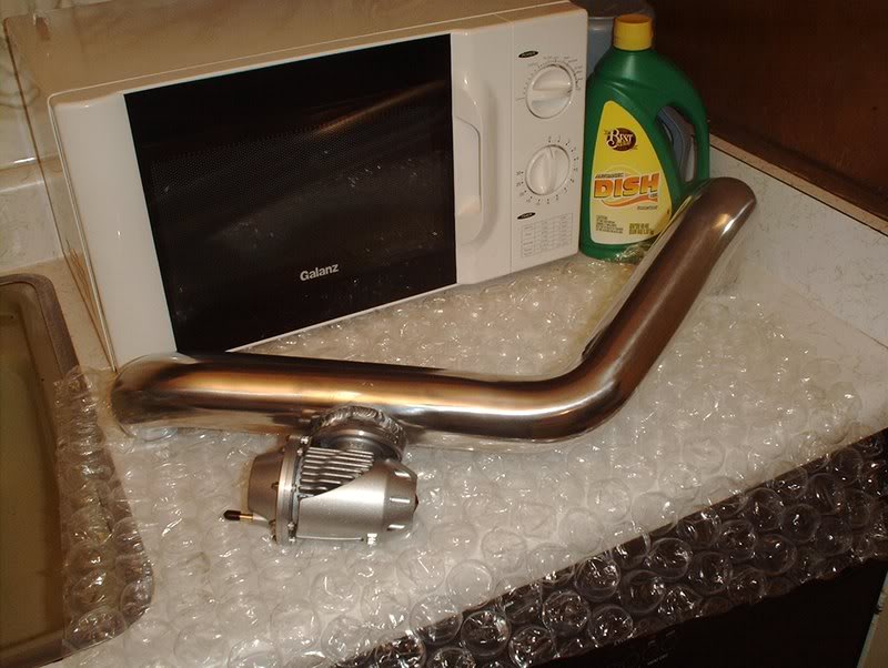
HKS hotpipe.
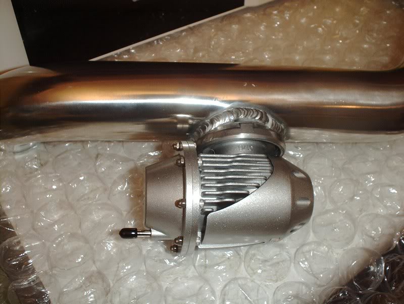
HKS SuperSequential Blow-off Valve.
I checked around and most of the hotpipes that I came across had a different pipe for the frontmount and the sidemount intercoolers. This HKS hotpipe can be used for both so if I ever decide to upgrade to a frontmount then I won't have to buy another hotpipe.
HKS hotpipe.
HKS SuperSequential Blow-off Valve.
I checked around and most of the hotpipes that I came across had a different pipe for the frontmount and the sidemount intercoolers. This HKS hotpipe can be used for both so if I ever decide to upgrade to a frontmount then I won't have to buy another hotpipe.
09-10-2008, 02:06 PM
#216
Contributing Member
Thread Starter
Join Date: Sep 2002
Location: Starkville, MS.
Posts: 1,192
Oil Filter Relocation Kit
I got a relocation kit in today.
Tools needed:
Crescent wrench
Socket wrench
11mm socket
13mm socket
Flathead screwdriver
Allen wrench
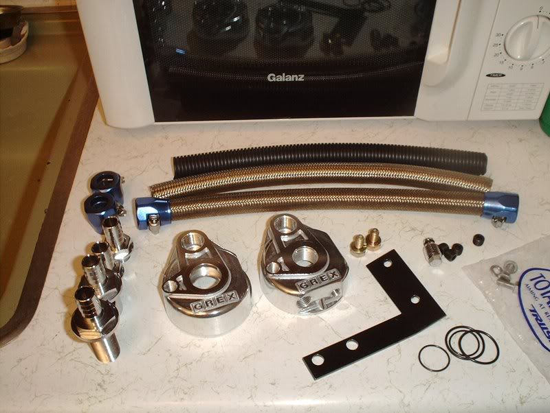
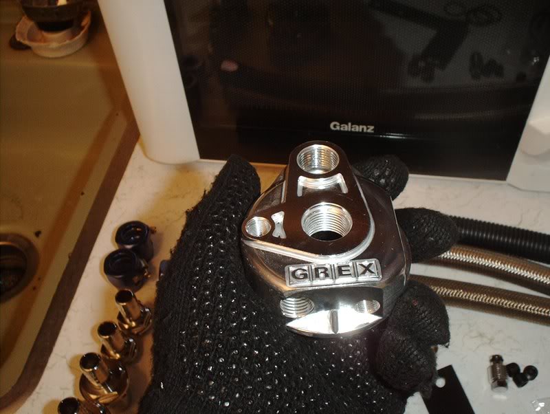
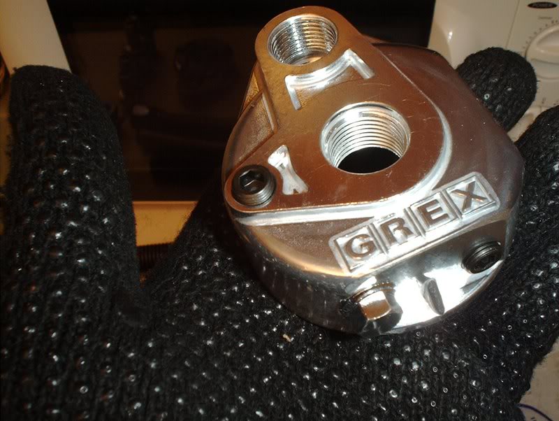
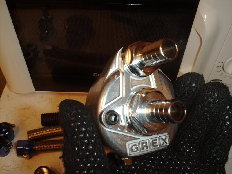
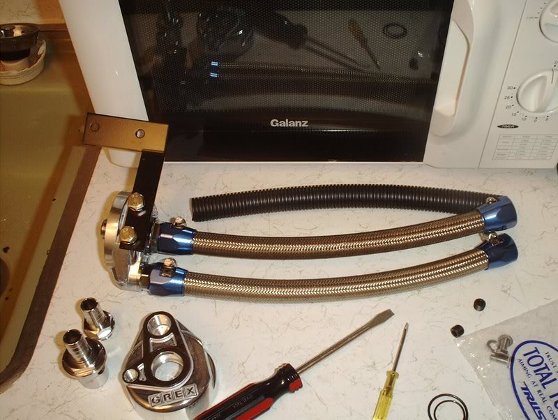
Greddy oil filter relocation kit
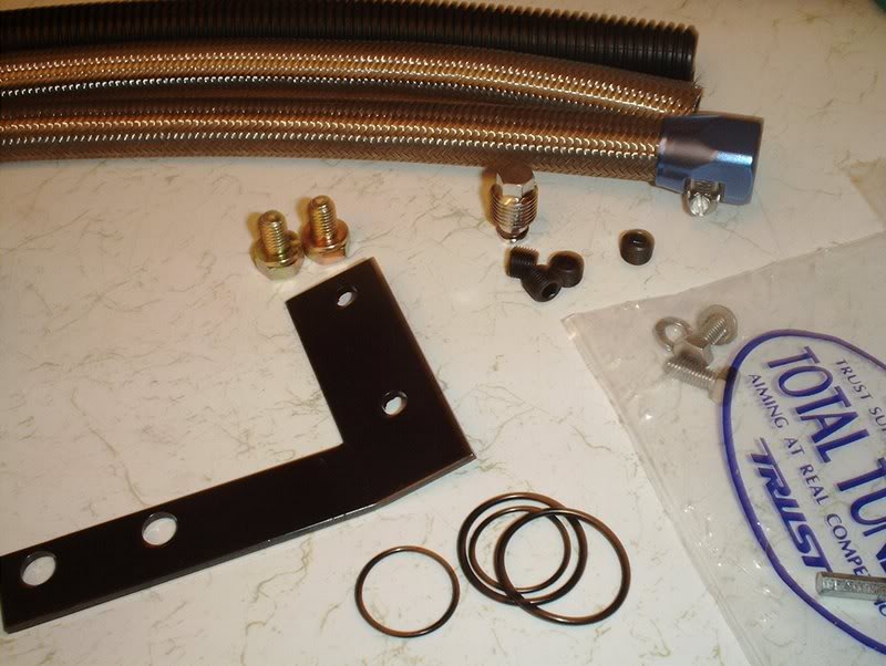
Hardware.
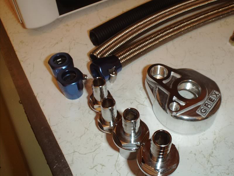
Fittings.
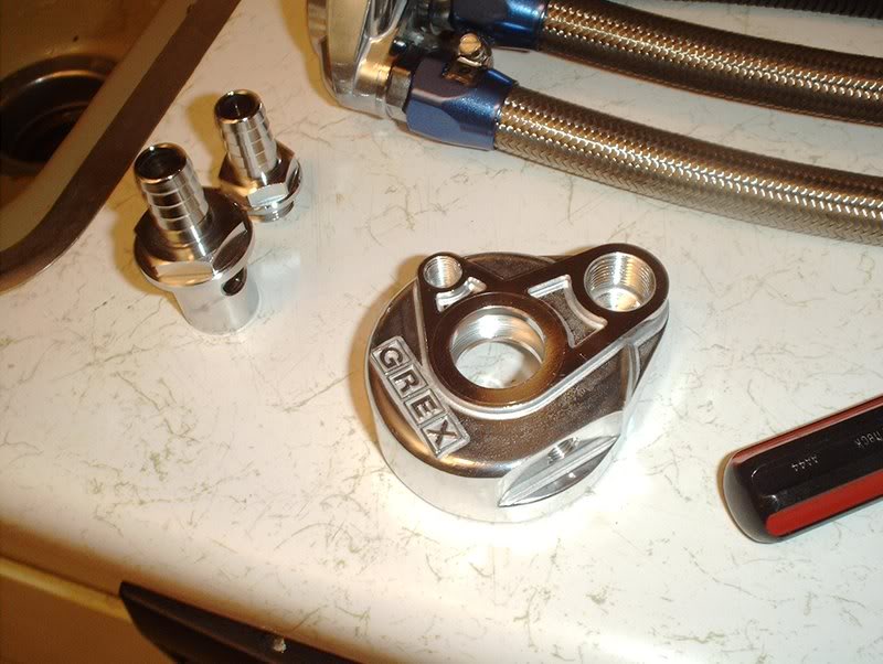
I started with with the oil filter side of the kit.
Use a allen wrench to plug up the two small ports and a 13 mm socket wrench for the larger port. I assume that these ports are used for a oil cooler kit and oil sensor(temp/pressure). There's also some ports on the other part of the kit.
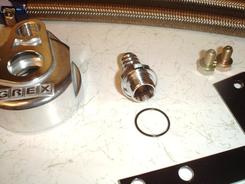
Take this nozzle and put on one of the gaskets.
Install it in the kit like so.
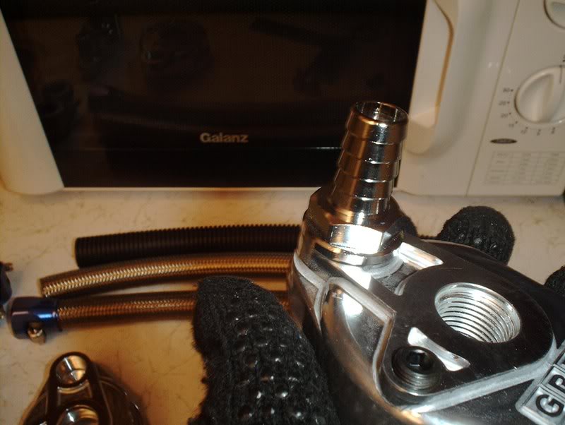
Take this nozzle and a gasket.
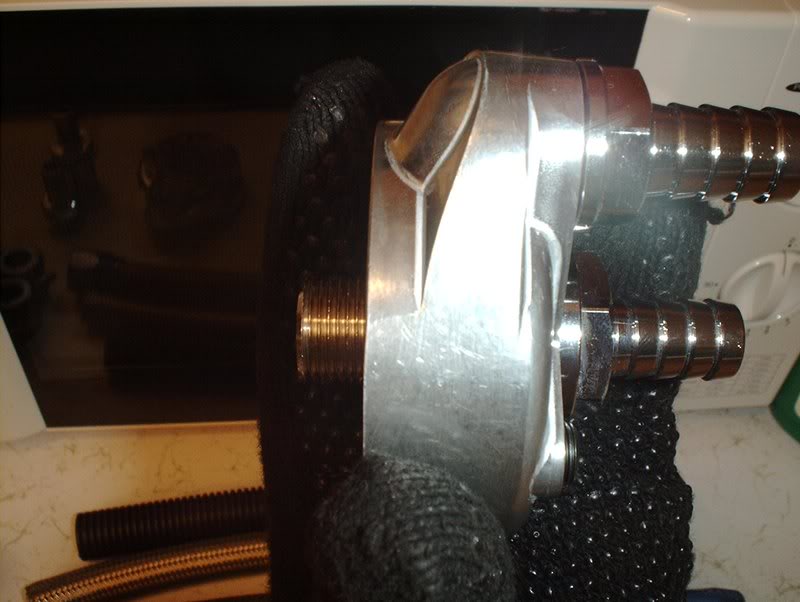
Screw the nozzle in.
You'll need deepwell 20mm and 23mm sockets to get over these nozzles but I didn't have any deepwell sockets of these sizes so I used a crescent wrench to tighten these nozzles. The instructions also didn't have any torque specs so I just cinched them down.
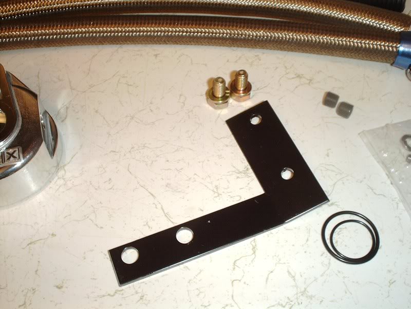
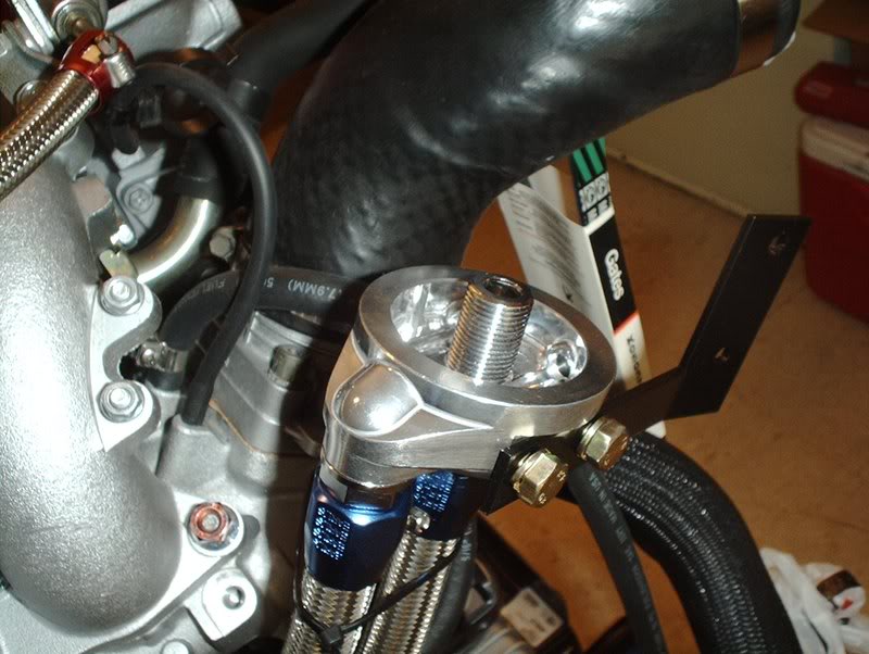
This bracket mounts to the oil filter side of the kit and bolts to your shock tower.
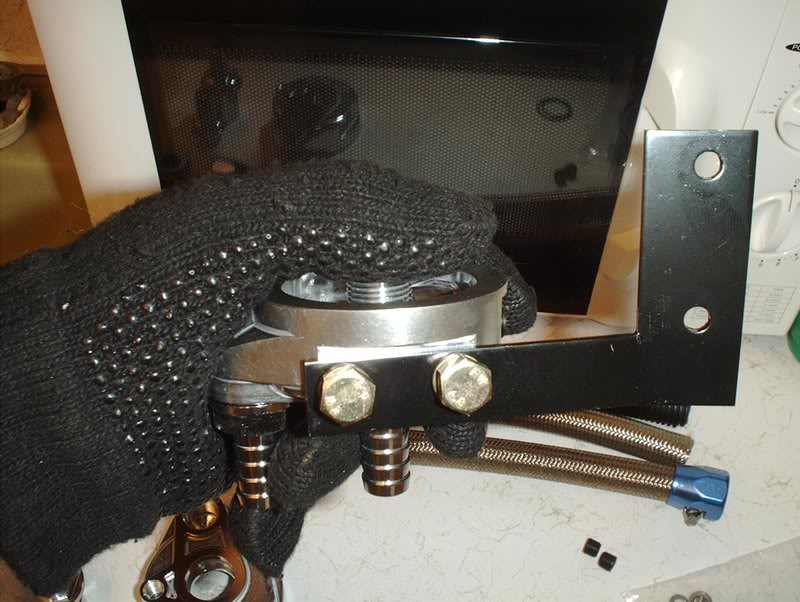
Use the provided bolts and a 11mm socket to mount this bracket on the side.
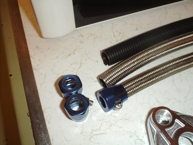
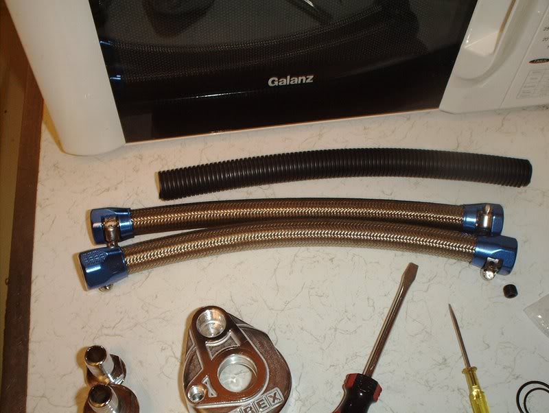
Next I got the hoses.
Place the fittings.
Place the hoses on the kit...
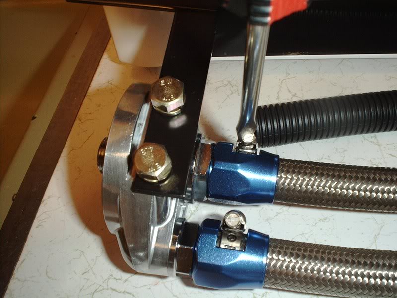
tighten with a flathead screwdriver.
Done with that.
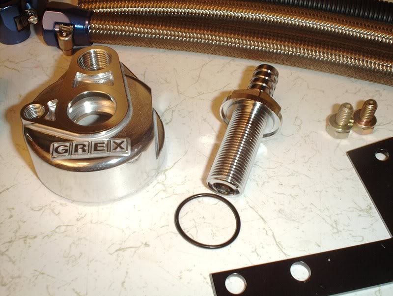
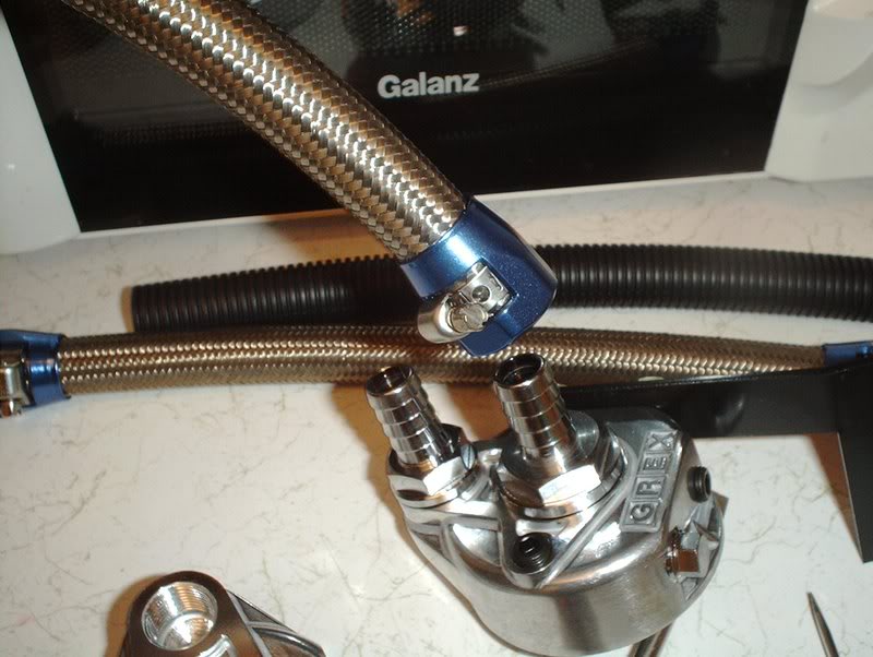
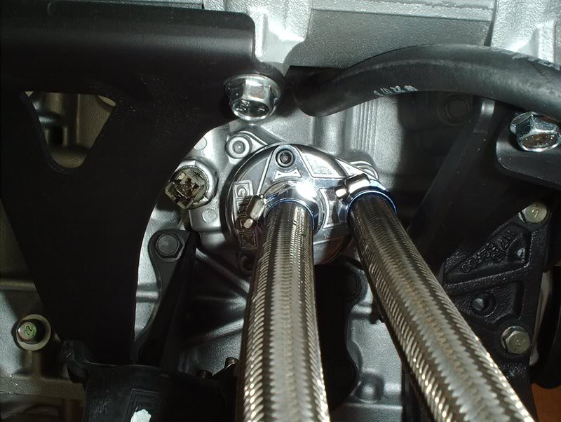
Now for the block side of the filter.
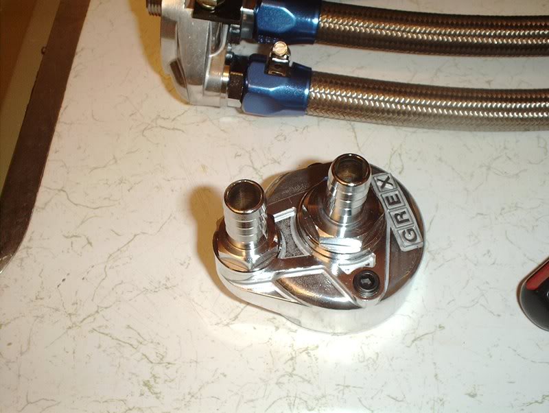
Go ahead and install the two nozzles with the provided gaskets and put them on the kit. There are two small ports on this side of the kit...oil sensors?
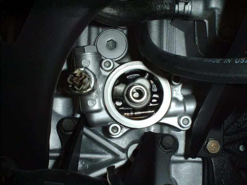
Stock oil filter location.
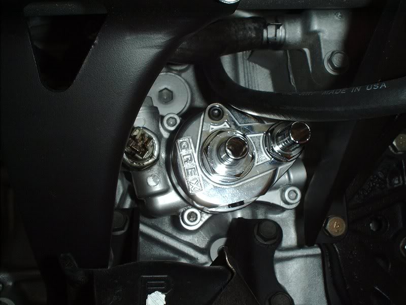
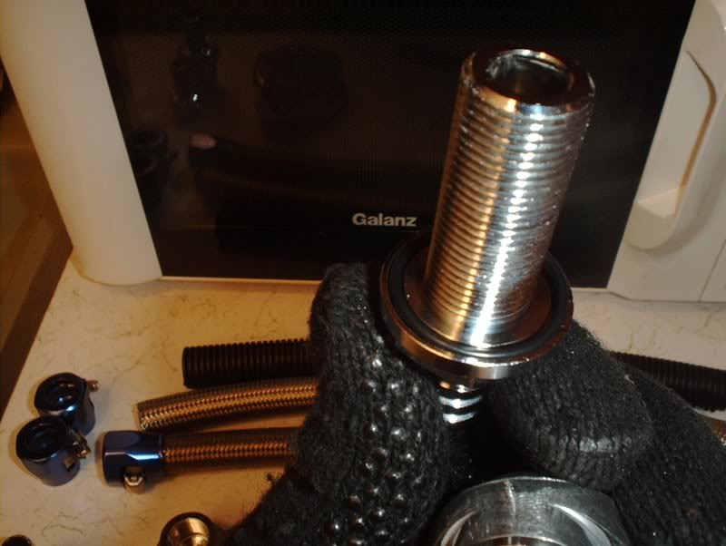
Mount the kit and screw the nozzle until tight.
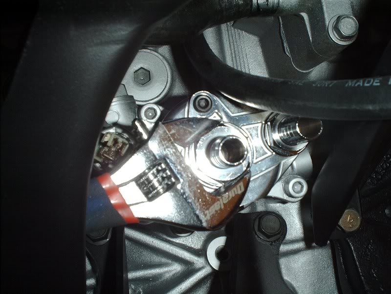
Use a crescent wrench to tighten.
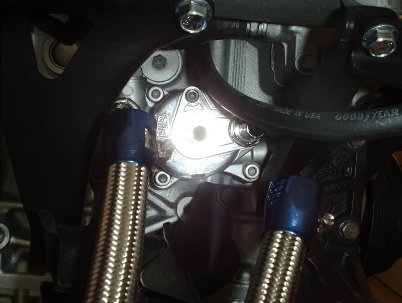
Take the other part of the kit...
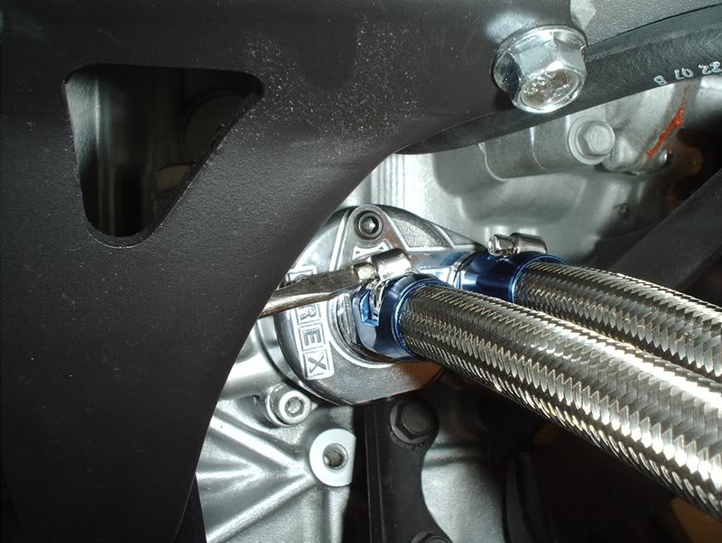
Mount the hoses on the plate and use your screwdriver to tighten.
I used a ziptie to support the kit to the engine until swap day.
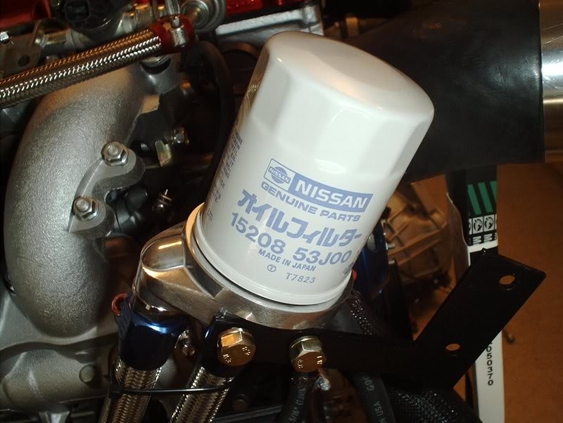
The fittings on this relocation kit are as follows...
-proper thread size 3/4-16UNF
-According to Greddy they recommend the Greddy QX-01 or QX-03 filter.
-They also have magnetic filter with the SX-01 or SX-03.
-You can also use 1985-87 Toyota Corolla GTS Oil Filter.
-The S13 Sr20 filter should also work.
I thought I was going to have to buy a different filter but the stock SR filters do work.
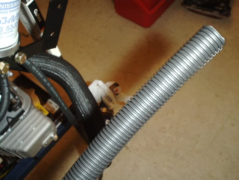
This hose cover came with the kit but where it goes...I don't know so I'm gonna let that part hang loose for now.
Tools needed:
Crescent wrench
Socket wrench
11mm socket
13mm socket
Flathead screwdriver
Allen wrench
Greddy oil filter relocation kit
Hardware.
Fittings.
I started with with the oil filter side of the kit.
Use a allen wrench to plug up the two small ports and a 13 mm socket wrench for the larger port. I assume that these ports are used for a oil cooler kit and oil sensor(temp/pressure). There's also some ports on the other part of the kit.
Take this nozzle and put on one of the gaskets.
Install it in the kit like so.
Take this nozzle and a gasket.
Screw the nozzle in.
You'll need deepwell 20mm and 23mm sockets to get over these nozzles but I didn't have any deepwell sockets of these sizes so I used a crescent wrench to tighten these nozzles. The instructions also didn't have any torque specs so I just cinched them down.
This bracket mounts to the oil filter side of the kit and bolts to your shock tower.
Use the provided bolts and a 11mm socket to mount this bracket on the side.
Next I got the hoses.
Place the fittings.
Place the hoses on the kit...
tighten with a flathead screwdriver.
Done with that.
Now for the block side of the filter.
Go ahead and install the two nozzles with the provided gaskets and put them on the kit. There are two small ports on this side of the kit...oil sensors?
Stock oil filter location.
Mount the kit and screw the nozzle until tight.
Use a crescent wrench to tighten.
Take the other part of the kit...
Mount the hoses on the plate and use your screwdriver to tighten.
I used a ziptie to support the kit to the engine until swap day.
The fittings on this relocation kit are as follows...
-proper thread size 3/4-16UNF
-According to Greddy they recommend the Greddy QX-01 or QX-03 filter.
-They also have magnetic filter with the SX-01 or SX-03.
-You can also use 1985-87 Toyota Corolla GTS Oil Filter.
-The S13 Sr20 filter should also work.
I thought I was going to have to buy a different filter but the stock SR filters do work.
This hose cover came with the kit but where it goes...I don't know so I'm gonna let that part hang loose for now.
09-14-2008, 10:18 AM
#218
Contributing Member
Thread Starter
Join Date: Sep 2002
Location: Starkville, MS.
Posts: 1,192
Need opinions on what type of boost controller to get. I've been reading up on many different brands and I'm lost...they all seem to have their pros and cons. So what's the electronic boost controller recommendation for a stock setup that will probably never see much adjustments in boost?
09-16-2008, 12:58 PM
#219
Contributing Member
Thread Starter
Join Date: Sep 2002
Location: Starkville, MS.
Posts: 1,192
Clutch...That Thing That Turns And Makes It Go!!!
Clutch kit...again! I had to ditch the first clutch so this time I got a Stage 2 Exedy that is sprung.
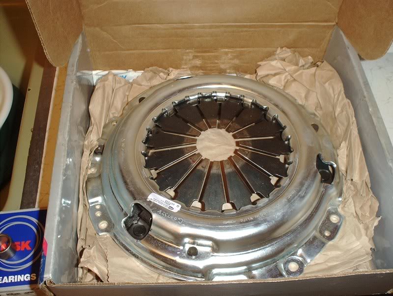
Pressure plate part#:06950B
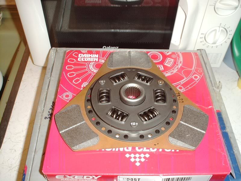
Clutch disc part#:ND05T
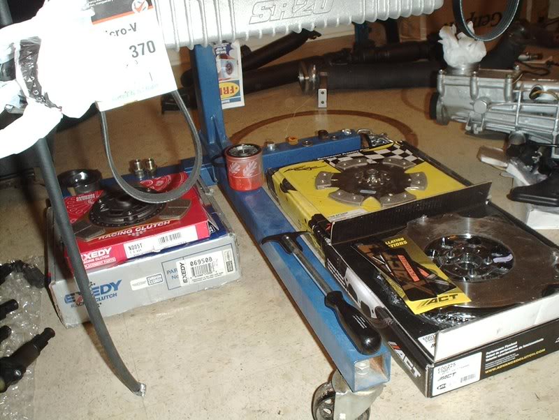
One more clutch kit and I can open up my own shop!
Pressure plate part#:06950B
Clutch disc part#:ND05T
One more clutch kit and I can open up my own shop!
 09-18-2008, 02:22 PM
#221
Contributing Member
Thread Starter
Join Date: Sep 2002
Location: Starkville, MS.
Posts: 1,192
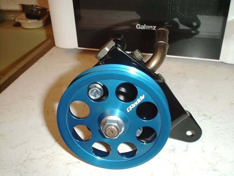
Power Steering Pump Installation???...
I've had every combination of P/S pump and bracket from here to Tucson so I finally thought that I had this pump situation complete.
Tools needed;
Socket wrench
Socket extension
14mm socket
17mm socket
Long socket extension
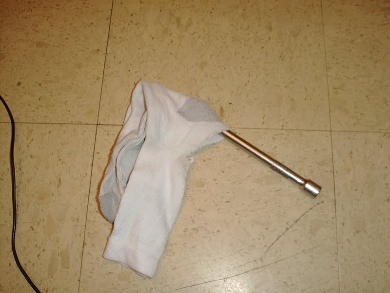
Old sock(Socko)
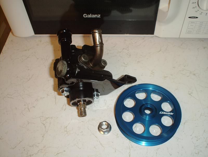
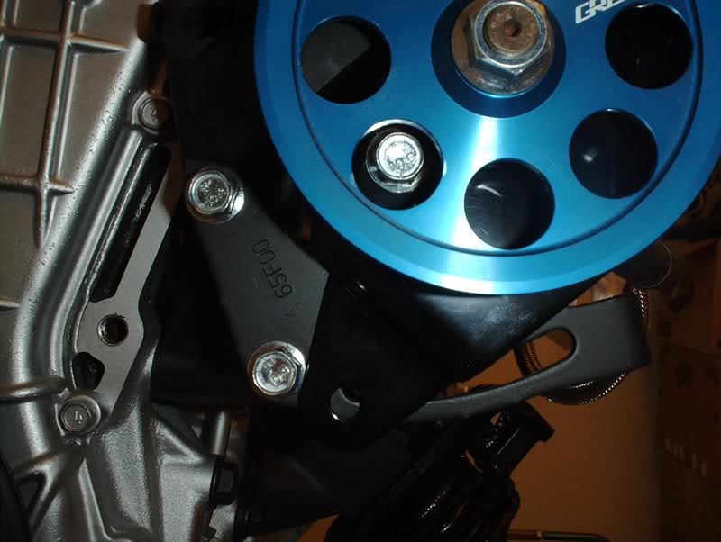
I finally got a SR pump with the right bracket so I can mount this pulley and be done with this.
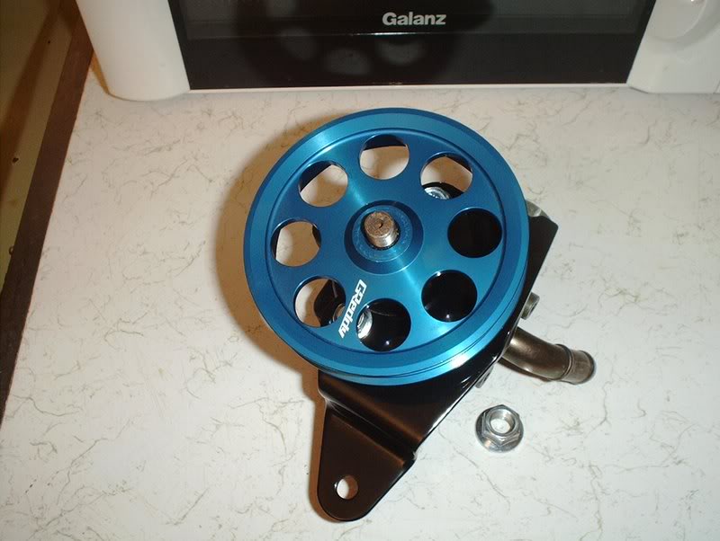
Mount the pulley...
Place the nut on.
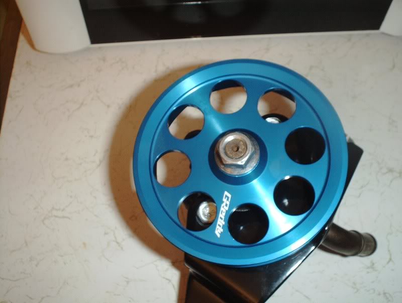
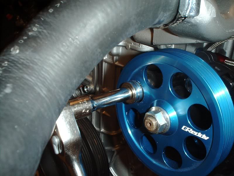
In order to keep the pulley from spinning while you tighten it...
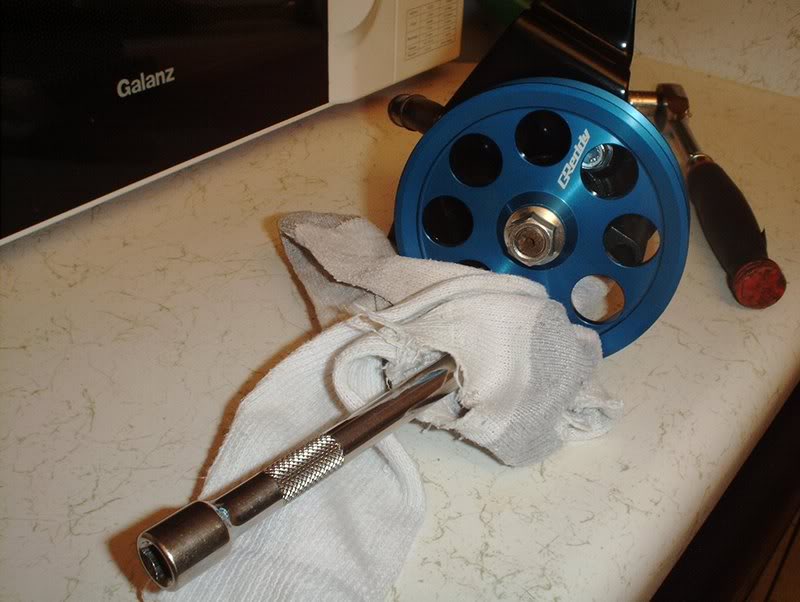
I took a socket extension and stuck it through one of the pulley holes.
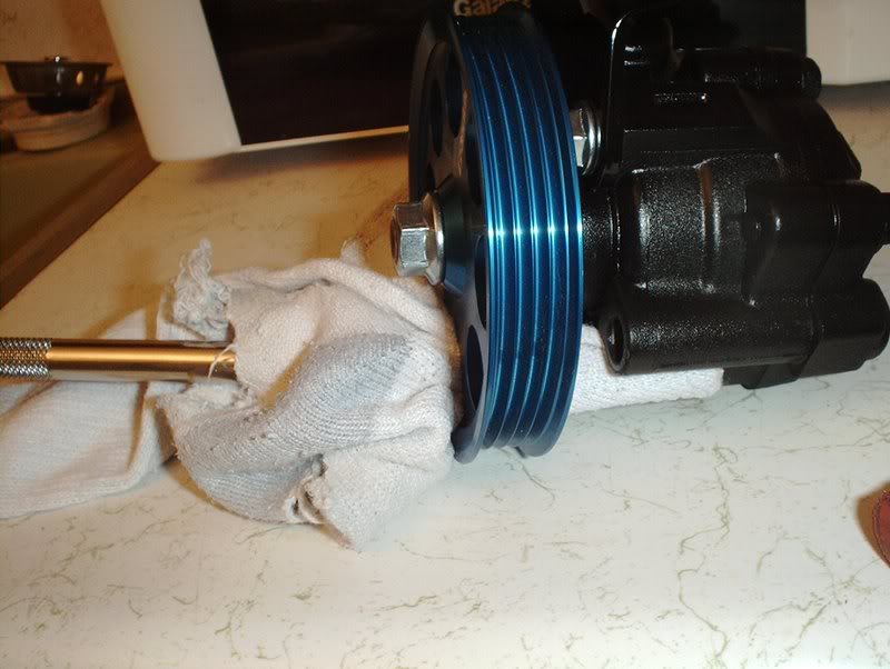
Put something soft on it to keep it from scratching or dinging up your pulley.
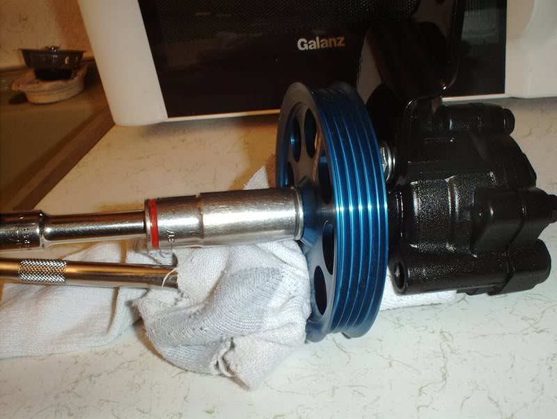
Take a 17mm socket and tighten the pulley.
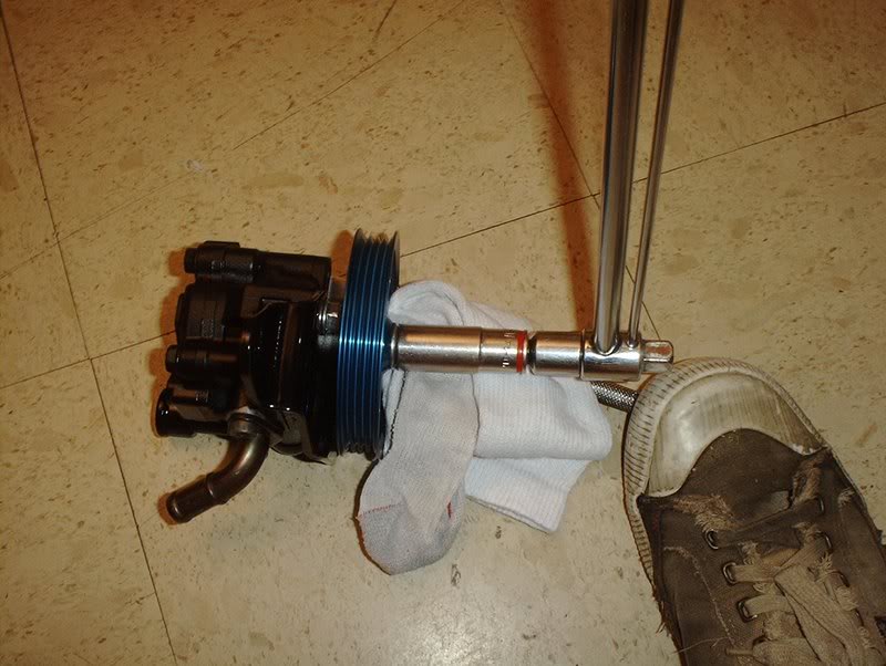
To torque it up just place it on the ground and use your foot to step on the extension to hold the pulley while you torque the nut to 50ft.lbs.
Done.
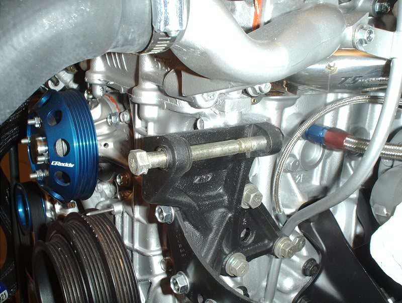
The pump is ready to be mounted to the block.
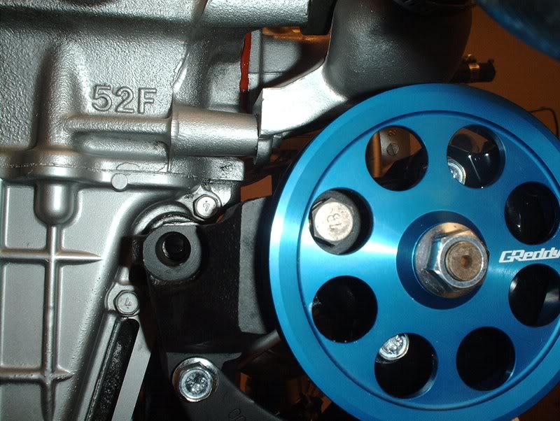
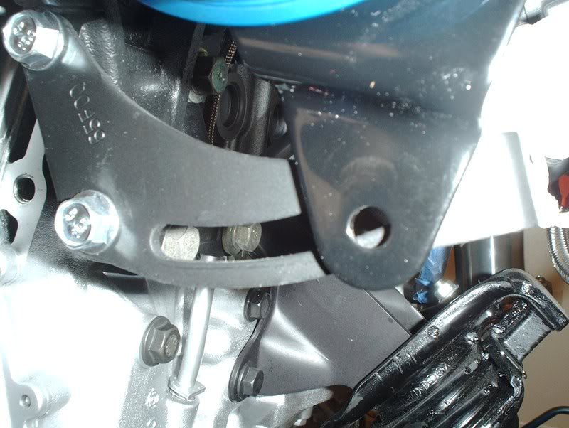
Mount it here and then spin it so you can tighten the mounting bolt.
Use a 14mm socket to torque to 23-31ft.lbs.
After all this trouble I still ran into yet another problem.
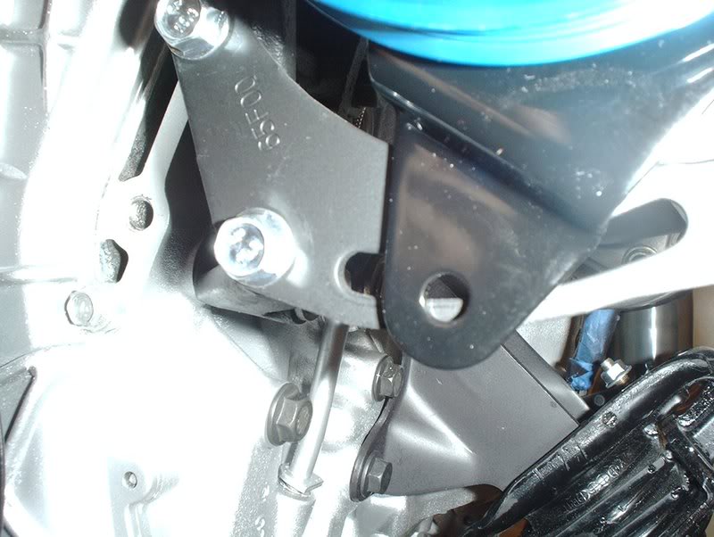
This P/S pump adjuster bracket seems to be the wrong one...doh!
TO BE CONTINUED!!!
Tools needed;
Socket wrench
Socket extension
14mm socket
17mm socket
Long socket extension
Old sock(Socko)
I finally got a SR pump with the right bracket so I can mount this pulley and be done with this.
Mount the pulley...
Place the nut on.
In order to keep the pulley from spinning while you tighten it...
I took a socket extension and stuck it through one of the pulley holes.
Put something soft on it to keep it from scratching or dinging up your pulley.
Take a 17mm socket and tighten the pulley.
To torque it up just place it on the ground and use your foot to step on the extension to hold the pulley while you torque the nut to 50ft.lbs.
Done.
The pump is ready to be mounted to the block.
Mount it here and then spin it so you can tighten the mounting bolt.
Use a 14mm socket to torque to 23-31ft.lbs.
After all this trouble I still ran into yet another problem.
This P/S pump adjuster bracket seems to be the wrong one...doh!
TO BE CONTINUED!!!
09-22-2008, 07:08 AM
#224
Contributing Member
Thread Starter
Join Date: Sep 2002
Location: Starkville, MS.
Posts: 1,192
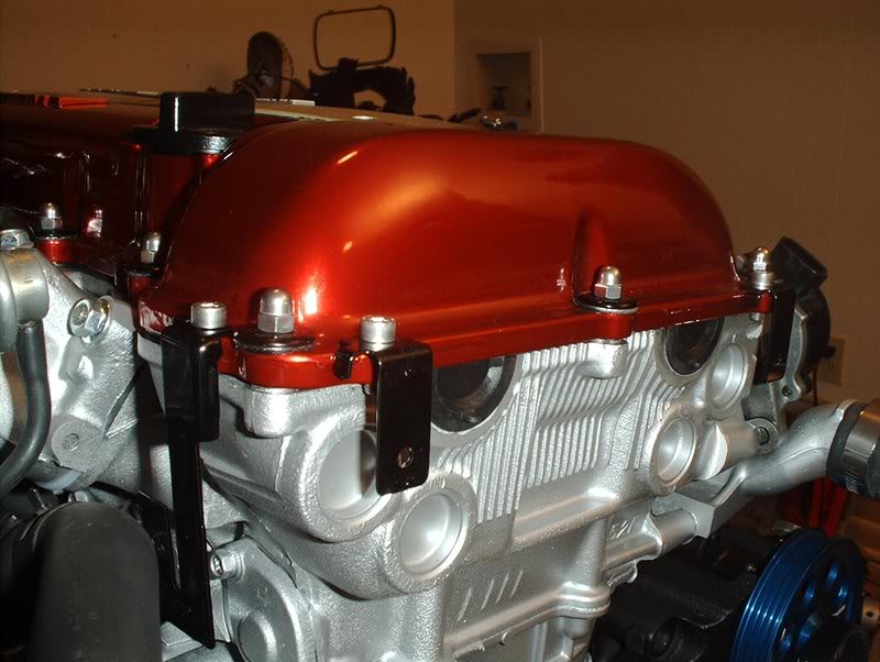
Valve Cover...Continued
I finally got that missing little o-ring/gasket in and a tube of ultra-grey so now I can install this valve cover.
Tools needed:
Socket wrench
Socket extension
10mm socket
Liquid gasket
Rags
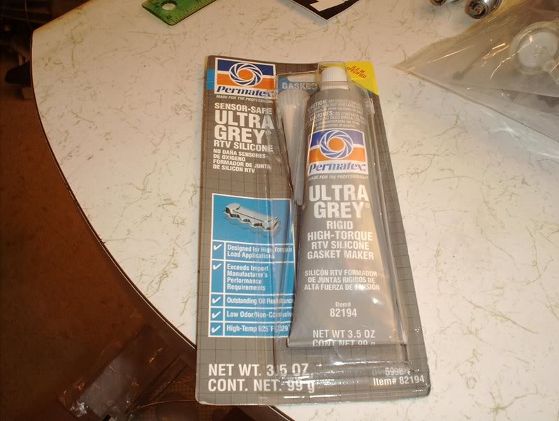
The FSM says to use a liquid gasket. I had the black and the red but people on many of the threads that I read up on were using the Permatex Ultra-Grey for this so that's what I chose.
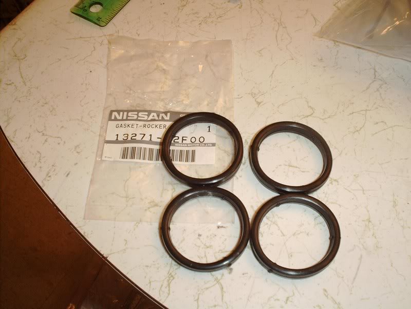
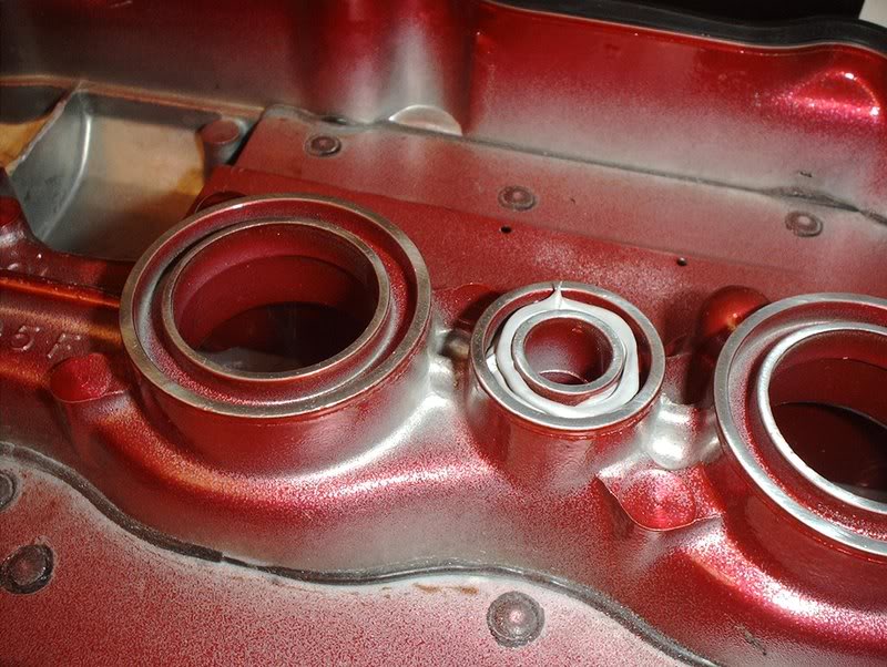
Spark Plug Gaskets part#: 13271-52F00
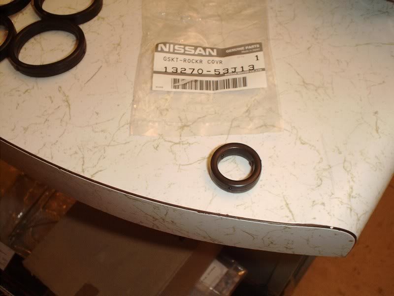
I'm still not sure what to call this one but it's refered to as "Gasket-Rocker Cover" part#: 13270-53J13.
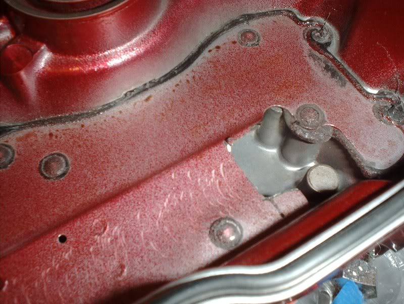
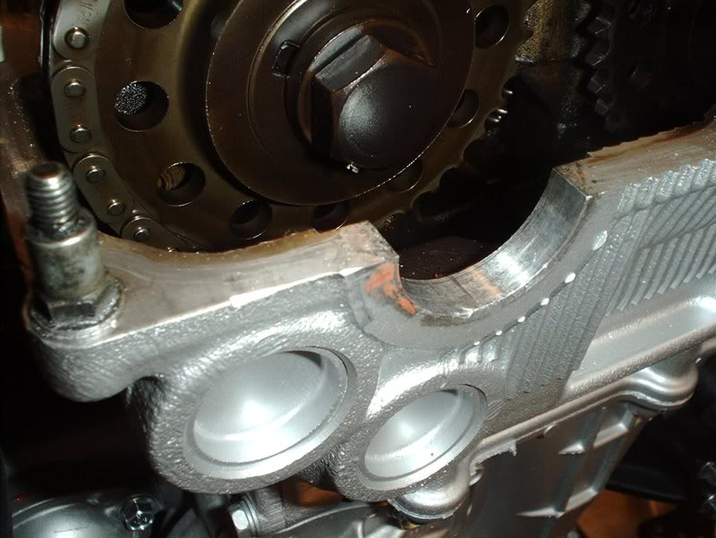
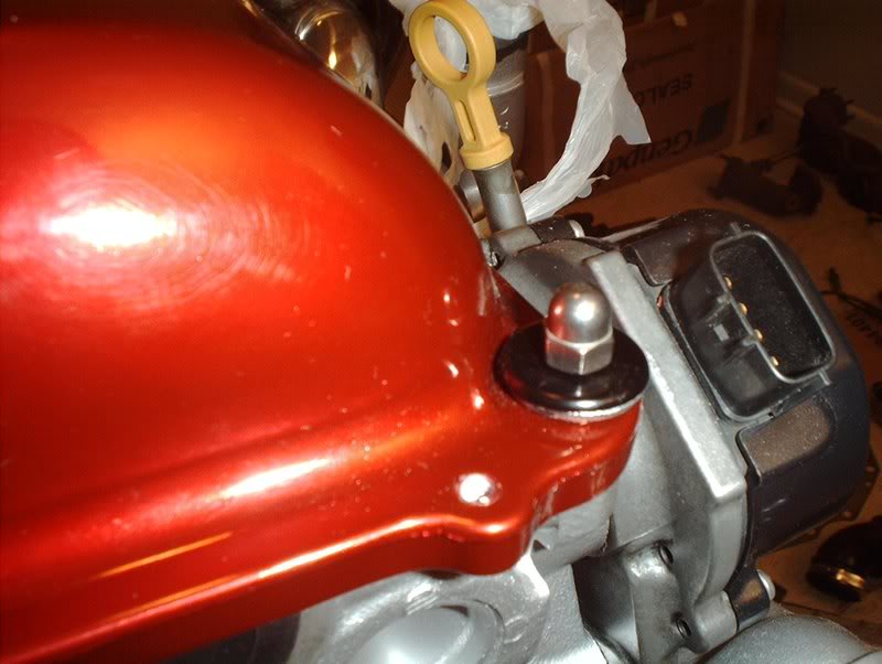
Like I said before, I had some trouble getting the valve cover to sit flush. Turns out one of the nuts on the oil tube, on the exhaust manifold side, was making contact with the valve cover so I took my dremel and made a cut to keep the tube from touching.
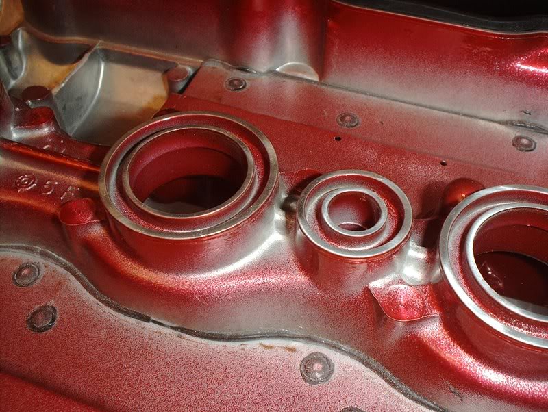
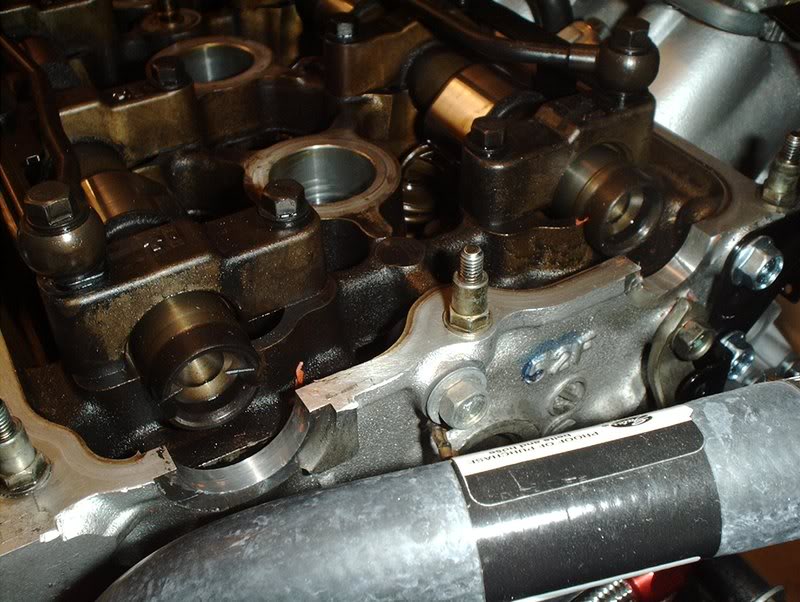
The gaskets will go here.
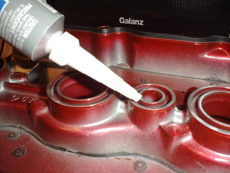
Take the ultra-grey...
and make a continuous bead on the valve cover and then place your gaskets.
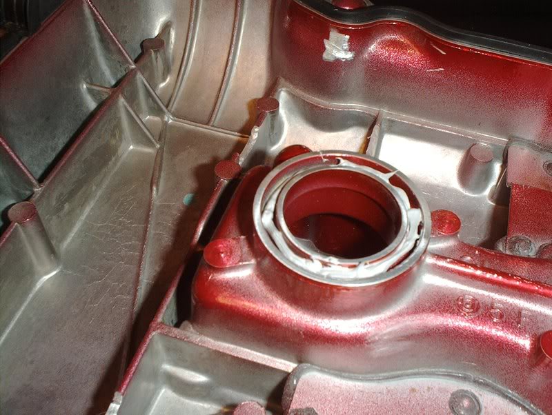
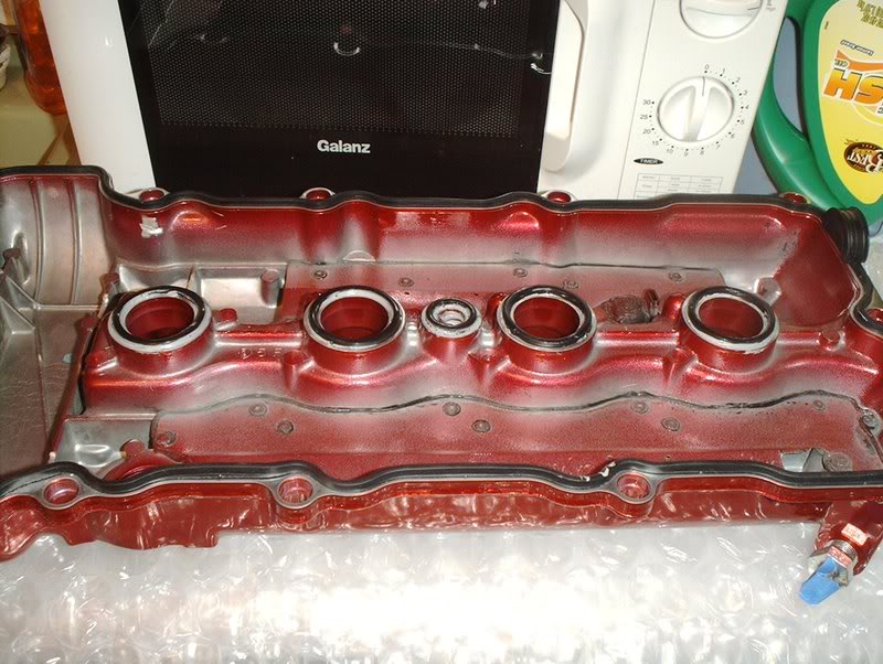
Wipe off any excess liquid gasket, I think I over did it on a couple. With all your gaskets and o-rings on it's time to put the cover on.
The FSM states to put a 3mm bead of liquid gasket on the four half moon sections of the block. Remove any traces of old gasket first.
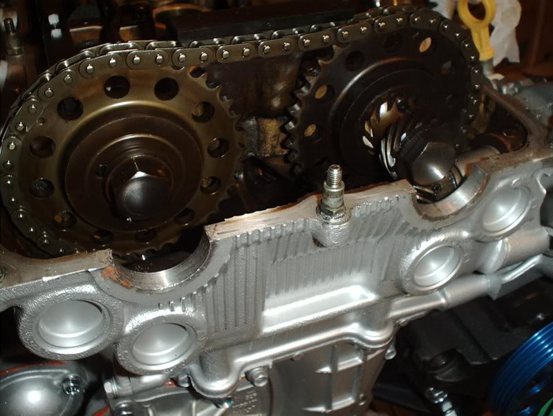
These two on the front...
and these two on the back.
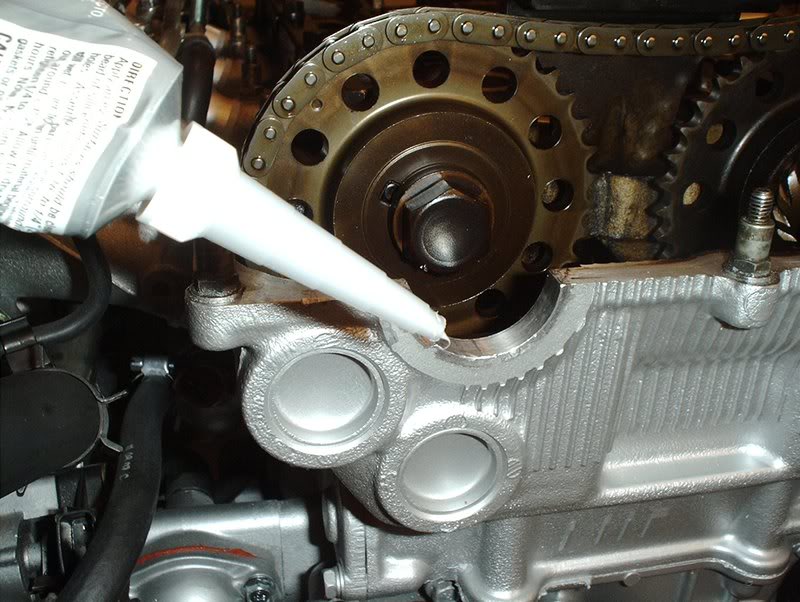
Take the liquid gasket and make a continuous bead on the half moons...
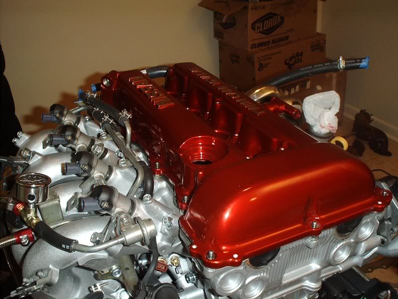
and place the valve cover on...yeah, that fuel pressure guage is on the wrong line.
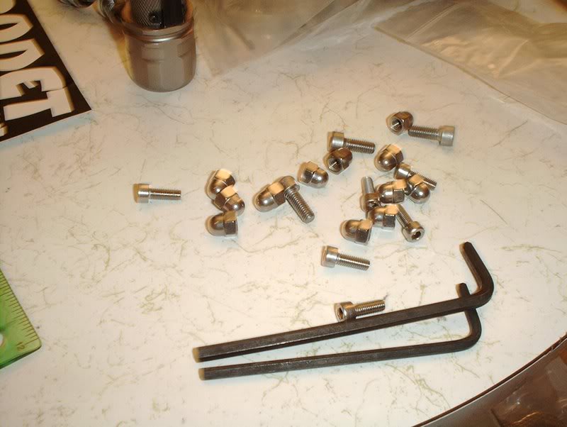
Get your hardware ready. Valve cover nuts.
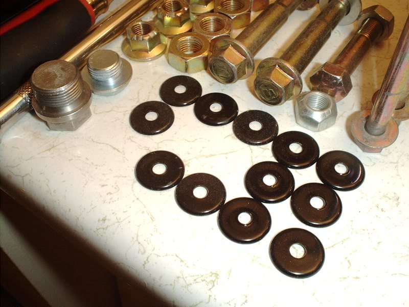
Valve cover washers.
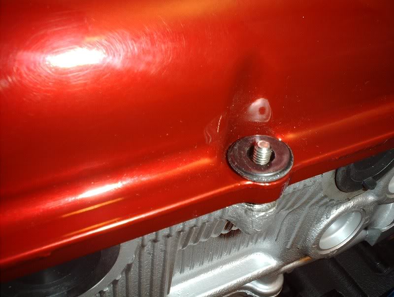
Place the rubber valve cover grommets on.
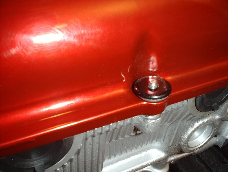
Place your valve cover washers on.
Place your valve cover nuts on. The valve cover nuts need to be tightened in a specific manner so refer to the FSM.
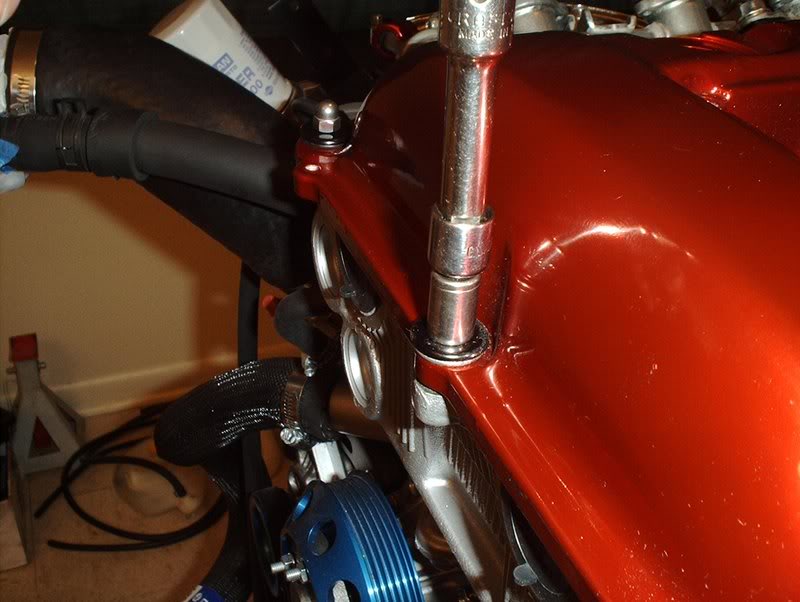
They get torqued to 2.9ft.lbs and then to 7.2ft.lbs.
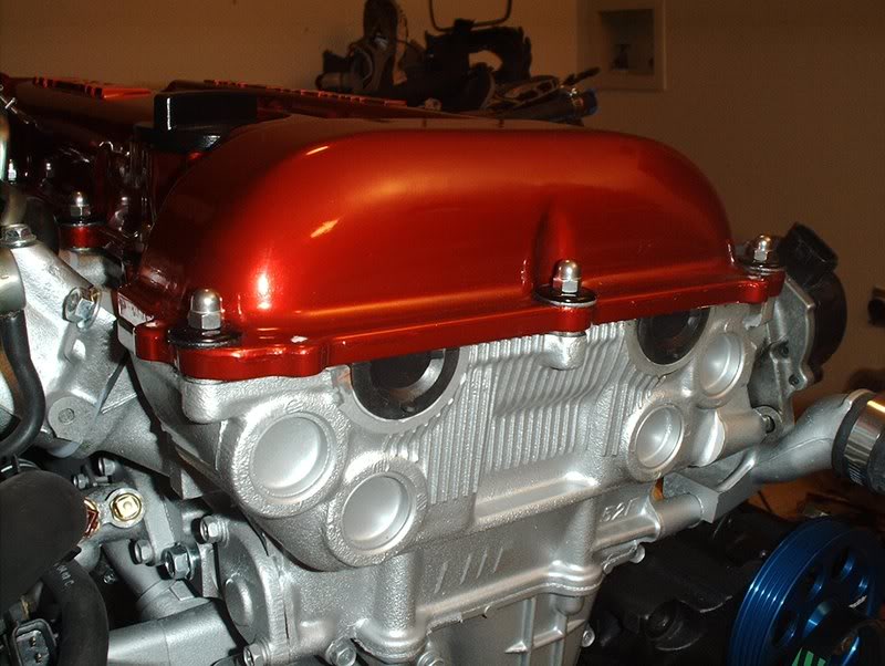
Completed.
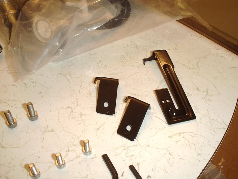
Next, your brackets for the coolant temp sensor harness and lines for the engine harness/throttlebody lines.
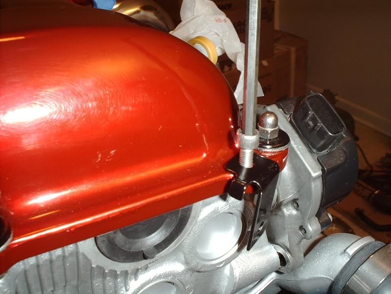
Place the brackets...
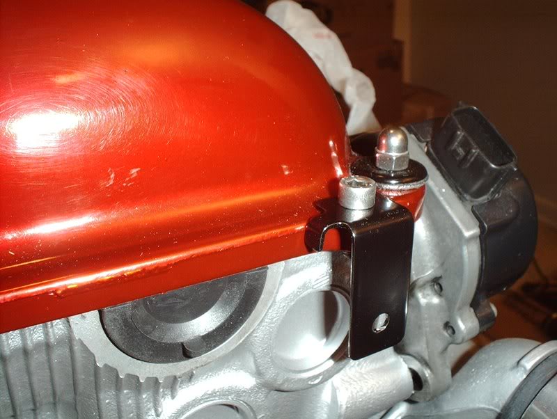
and tighten
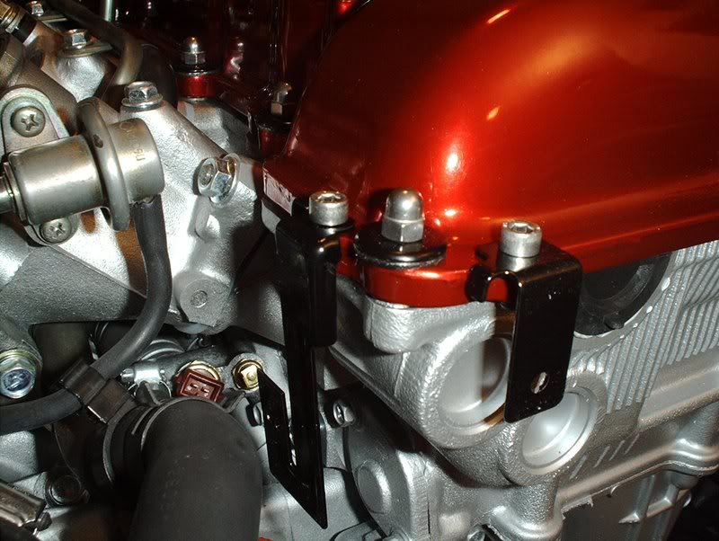
Done with that.
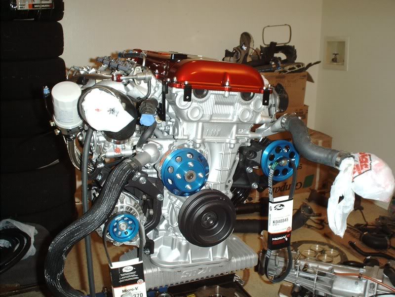
Complete.
Tools needed:
Socket wrench
Socket extension
10mm socket
Liquid gasket
Rags
The FSM says to use a liquid gasket. I had the black and the red but people on many of the threads that I read up on were using the Permatex Ultra-Grey for this so that's what I chose.
Spark Plug Gaskets part#: 13271-52F00
I'm still not sure what to call this one but it's refered to as "Gasket-Rocker Cover" part#: 13270-53J13.
Like I said before, I had some trouble getting the valve cover to sit flush. Turns out one of the nuts on the oil tube, on the exhaust manifold side, was making contact with the valve cover so I took my dremel and made a cut to keep the tube from touching.
The gaskets will go here.
Take the ultra-grey...
and make a continuous bead on the valve cover and then place your gaskets.
Wipe off any excess liquid gasket, I think I over did it on a couple. With all your gaskets and o-rings on it's time to put the cover on.
The FSM states to put a 3mm bead of liquid gasket on the four half moon sections of the block. Remove any traces of old gasket first.
These two on the front...
and these two on the back.
Take the liquid gasket and make a continuous bead on the half moons...
and place the valve cover on...yeah, that fuel pressure guage is on the wrong line.
Get your hardware ready. Valve cover nuts.
Valve cover washers.
Place the rubber valve cover grommets on.
Place your valve cover washers on.
Place your valve cover nuts on. The valve cover nuts need to be tightened in a specific manner so refer to the FSM.
They get torqued to 2.9ft.lbs and then to 7.2ft.lbs.
Completed.
Next, your brackets for the coolant temp sensor harness and lines for the engine harness/throttlebody lines.
Place the brackets...
and tighten
Done with that.
Complete.
09-26-2008, 07:40 AM
#225
Contributing Member
Thread Starter
Join Date: Sep 2002
Location: Starkville, MS.
Posts: 1,192
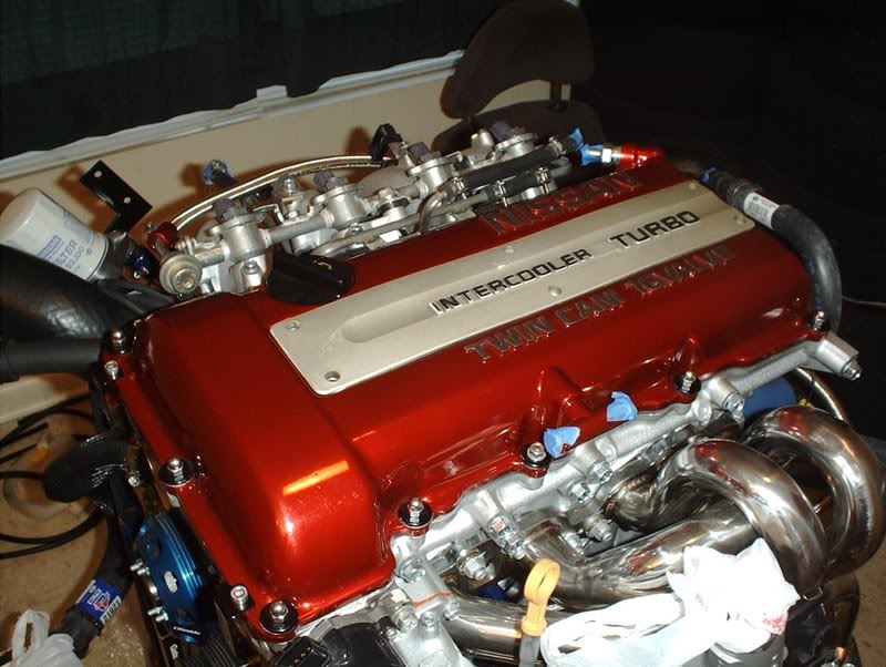
O2 Sensor
I recieved my O2 sensor this morning.
Tools needed:
17mm wrench
O2 sensor socket
Socket wrench
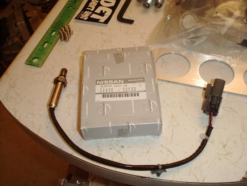
OEM "skinny type" O2 sensor part#: 22690-50F00.
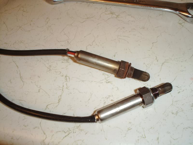
Old sensor vs. new sensor
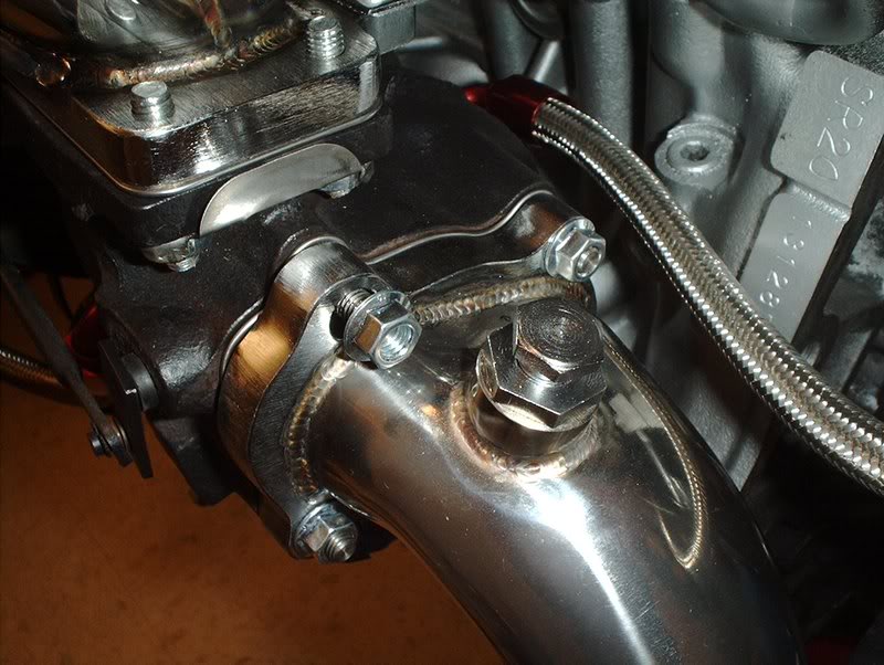
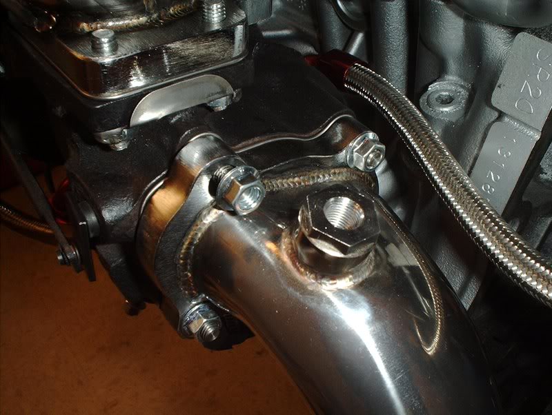
The sensor goes here in the turbo outlet.
Remove the sensor bung from the adapter.
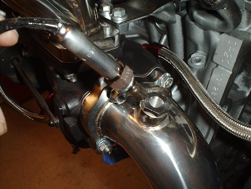
Place the sensor and screw on tight.
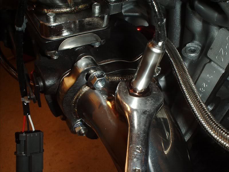
I used a 17mm wrench to tighten. You'll need a O2 sensor socket to tighten to spec with your torque wrench. It gets torqued to 30-44 ft.lbs.

Complete. I am officially done with the exhaust and the intake sides of the block...as far as I know.
Tools needed:
17mm wrench
O2 sensor socket
Socket wrench
OEM "skinny type" O2 sensor part#: 22690-50F00.
Old sensor vs. new sensor
The sensor goes here in the turbo outlet.
Remove the sensor bung from the adapter.
Place the sensor and screw on tight.
I used a 17mm wrench to tighten. You'll need a O2 sensor socket to tighten to spec with your torque wrench. It gets torqued to 30-44 ft.lbs.
Complete. I am officially done with the exhaust and the intake sides of the block...as far as I know.