
My S13 SR20DET Prep

Thread Starter
Contributing Member
Joined: Sep 2002
Posts: 1,192
From: Starkville, MS.
Front Main Oil Seal Replacement
I got my hands on a pulley puller so I could finally replace that front main seal. I tried using a prybar to work the loosened pulley off but I couldn't get it to move without putting a lot of English on it and I didn't want to risk cracking the oil pump front cover.
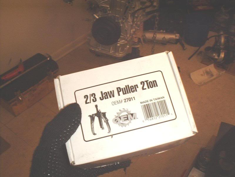
3 jaw pulley puller-AutoZone loan a tool program.
Looks like this.
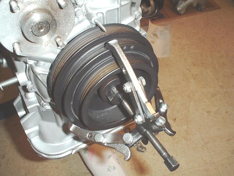
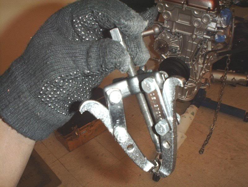
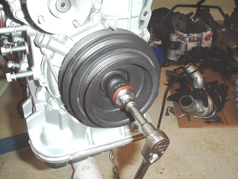
Just take the puller and hook the legs on the pulley and get the big screw on your crank pulley bolt. The forum says to have the crank pulley bolt threaded in a tad and to place the puller legs on the 2nd or 3rd ridges of the crank pulley rather than the first.
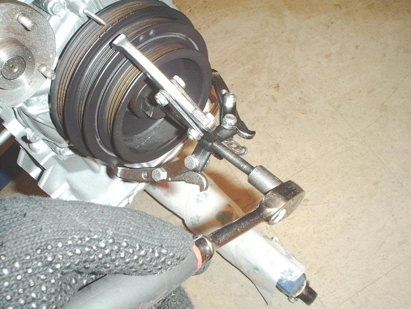
Use a 13mm socket to crank on the pulley...
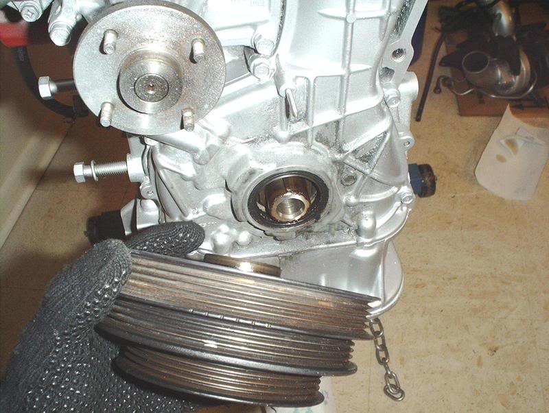
until the puller pops it free. You'll be able to see the crank pulley as it gets backed off the crank while you turn the pulley puller.
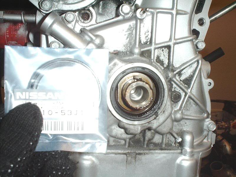
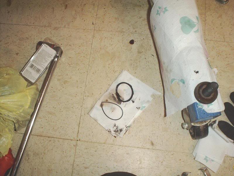
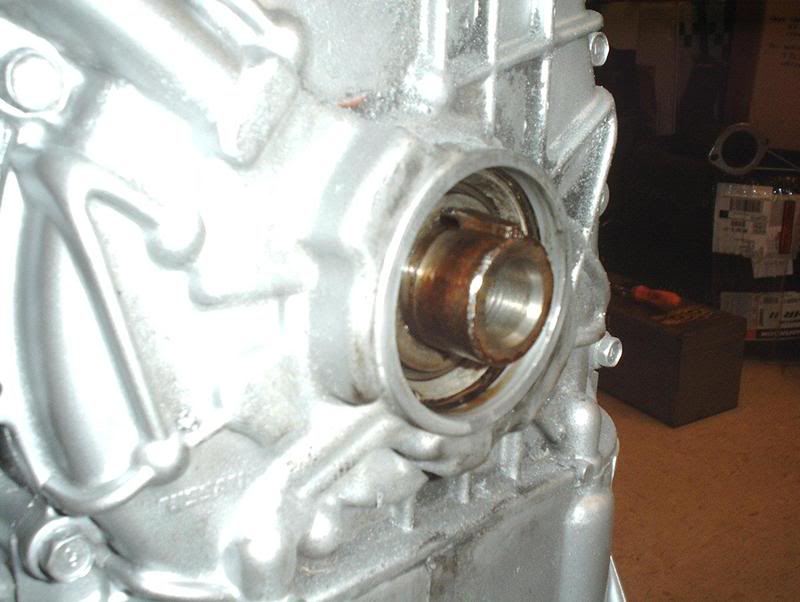
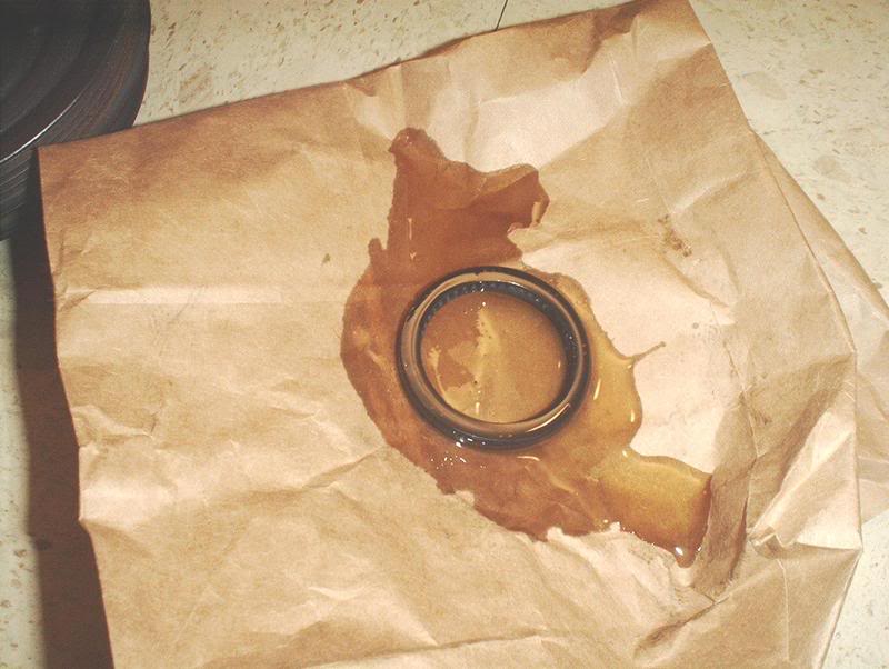
Front main oil seal. Part#13510-53J10
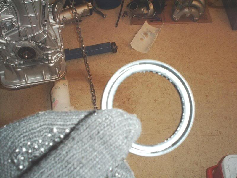
The oil seal has two sides that are different and it has to be placed in a specific way so make sure you get it right the first time. This is the side that goes in towards the engine, notice the big grooves...
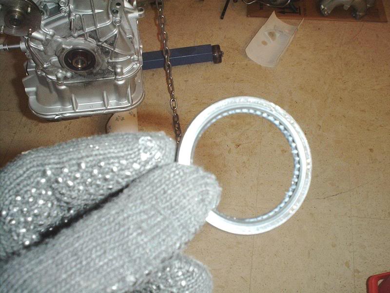
and this is the side that goes outward toward the front of the car.
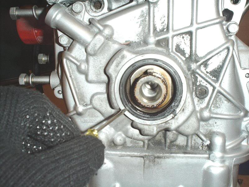
I first tried to remove the old main seal with a small flathead screwdriver, be careful not to ding or scrape the crank says the FSM. I couldn't really get it out with this small screwdriver. This made me very uncomfortable when I couldn't get it out because I know this is a sensitive area on the engine and I didn't want to damage anything or mess this up. I tried to work the screwdriver around the seal and then tried to pry out the outer edges but only managed to tear it slightly.
It started to come apart after I ripped it
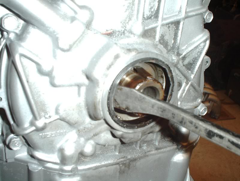
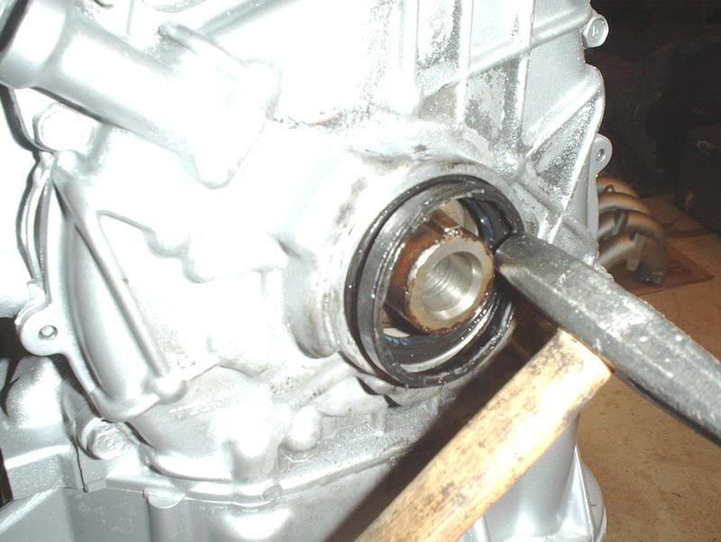
After trying that I got a prybar and in a clockwise motion was able to wedge the main seal out one side at a time...
until it popped out.
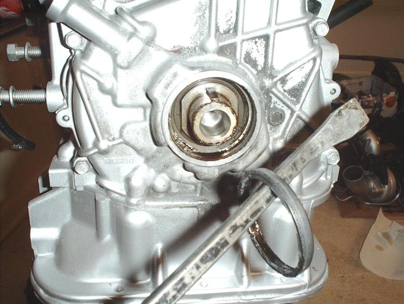
I took the new seal and oiled it up and inserted it on the crank.
The FSM says to use a seal driver or an appropriate tool to install the new seal which I didn't have so I just used the old seal. After getting the new front main seal in place, I positioned the old seal directly on top of it and used a small hammer to pop it into place. These seals are very hard so it was quite solid for the poundometer to do it's thing.
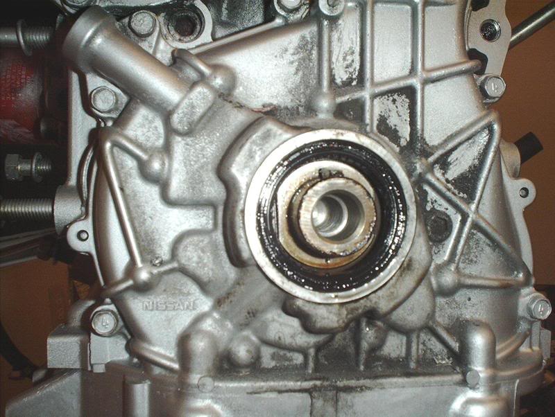
Got it in, checked it to see if it was seated correctly and lined up. Good to go.
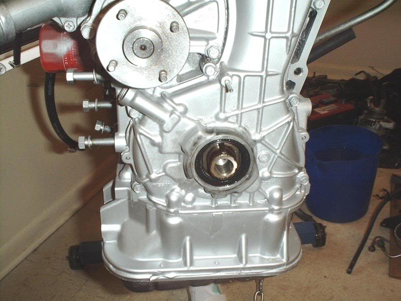
Now is a perfect time to clean this area which is hard to get to with the crank pulley on.
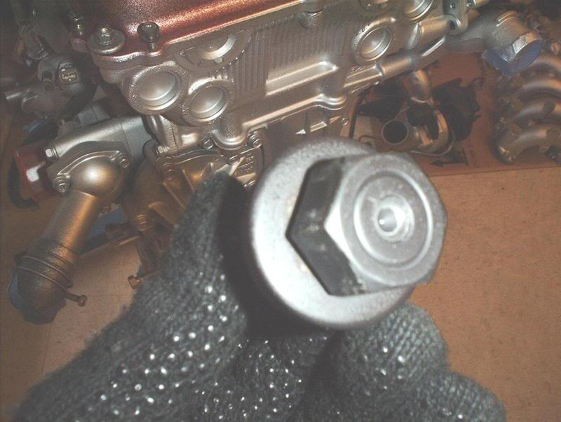
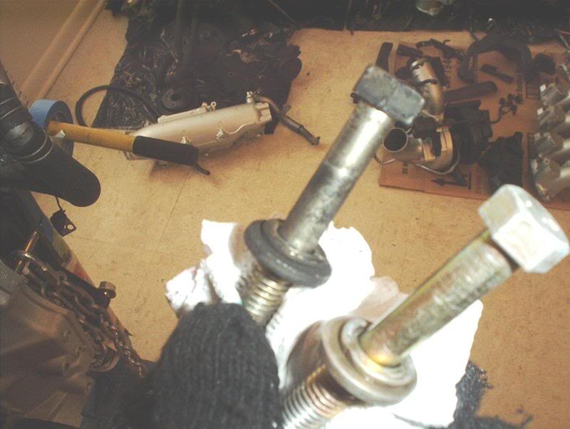
I would advise anyone who attempts this to place a piece of metal between your crank pulley bolt and the puller screw to keep this from happening to your crank pulley bolt when you turn the puller screw. It dug into my crank pulley bolt slightly.
I put the crank pulley back on. I was worried about mounting the pulley back on...what about the timing marks, how is this pulley going to get back to it's original position? What I hadn't realized was that the crank pulley has a indention on it that matches up with the crank so it only mounts on one way which is how it remains in it's original position so problem solved. I'm going to get a lightweight underdrive pulley so I just barely put the stock pulley back on without torquing it down.
The crank pulley is torqued to 105-112ft.lbs.
*I later decided to opt out of getting a lightweight crank pulley.
A SEAL PULLER AND SEAL DRIVER KIT IS HIGHLY RECOMMENDED FOR REPLACING YOUR SEALS!!! I DIDN'T HAVE ONE WHEN I DID THIS SEAL AND I REGRET IT!
I was very nervous about doing this so if anyone who has done it before sees something that I did wrong then please let me know.
3 jaw pulley puller-AutoZone loan a tool program.
Looks like this.
Just take the puller and hook the legs on the pulley and get the big screw on your crank pulley bolt. The forum says to have the crank pulley bolt threaded in a tad and to place the puller legs on the 2nd or 3rd ridges of the crank pulley rather than the first.
Use a 13mm socket to crank on the pulley...
until the puller pops it free. You'll be able to see the crank pulley as it gets backed off the crank while you turn the pulley puller.
Front main oil seal. Part#13510-53J10
The oil seal has two sides that are different and it has to be placed in a specific way so make sure you get it right the first time. This is the side that goes in towards the engine, notice the big grooves...
and this is the side that goes outward toward the front of the car.
I first tried to remove the old main seal with a small flathead screwdriver, be careful not to ding or scrape the crank says the FSM. I couldn't really get it out with this small screwdriver. This made me very uncomfortable when I couldn't get it out because I know this is a sensitive area on the engine and I didn't want to damage anything or mess this up. I tried to work the screwdriver around the seal and then tried to pry out the outer edges but only managed to tear it slightly.
It started to come apart after I ripped it
After trying that I got a prybar and in a clockwise motion was able to wedge the main seal out one side at a time...
until it popped out.
I took the new seal and oiled it up and inserted it on the crank.
The FSM says to use a seal driver or an appropriate tool to install the new seal which I didn't have so I just used the old seal. After getting the new front main seal in place, I positioned the old seal directly on top of it and used a small hammer to pop it into place. These seals are very hard so it was quite solid for the poundometer to do it's thing.
Got it in, checked it to see if it was seated correctly and lined up. Good to go.
Now is a perfect time to clean this area which is hard to get to with the crank pulley on.
I would advise anyone who attempts this to place a piece of metal between your crank pulley bolt and the puller screw to keep this from happening to your crank pulley bolt when you turn the puller screw. It dug into my crank pulley bolt slightly.
I put the crank pulley back on. I was worried about mounting the pulley back on...what about the timing marks, how is this pulley going to get back to it's original position? What I hadn't realized was that the crank pulley has a indention on it that matches up with the crank so it only mounts on one way which is how it remains in it's original position so problem solved. I'm going to get a lightweight underdrive pulley so I just barely put the stock pulley back on without torquing it down.
The crank pulley is torqued to 105-112ft.lbs.
*I later decided to opt out of getting a lightweight crank pulley.
A SEAL PULLER AND SEAL DRIVER KIT IS HIGHLY RECOMMENDED FOR REPLACING YOUR SEALS!!! I DIDN'T HAVE ONE WHEN I DID THIS SEAL AND I REGRET IT!
I was very nervous about doing this so if anyone who has done it before sees something that I did wrong then please let me know.
Last edited by positron; May 13, 2008 at 09:42 AM.
Thread Starter
Contributing Member
Joined: Sep 2002
Posts: 1,192
From: Starkville, MS.
Thermostat
Today I got bored so I swapped out the thermostat.
Tools needed:
Socket wrench
Socket extension
10mm socket
Liquid gasket
Razorblade
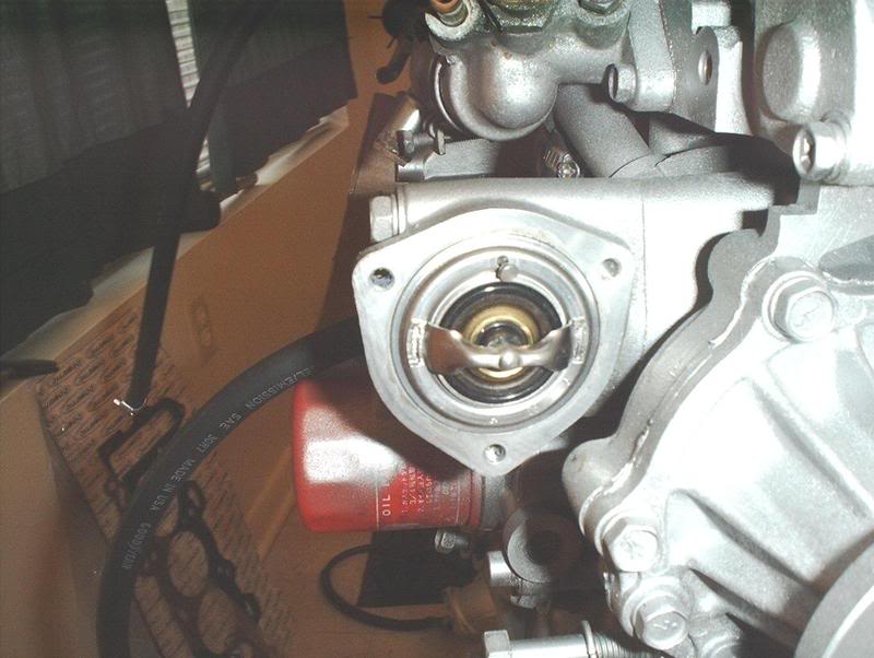
Water outlet houses the thermostat.
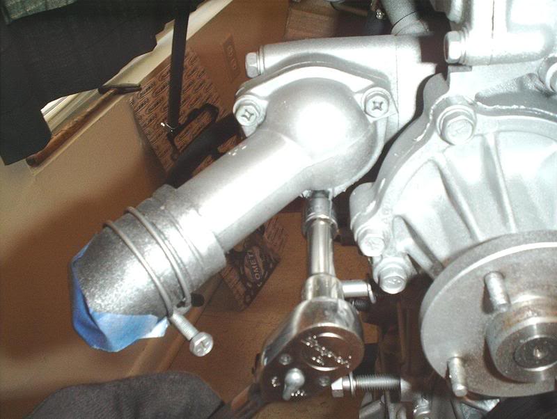
Use a 10mm socket to remove the water outlet.
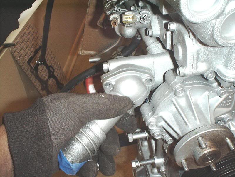
After I removed the bolts I had to man-up on the water outlet to bust it loose.
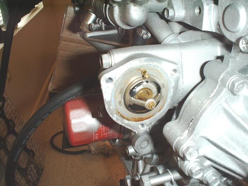
OEM thermostat. Note the position of the jiggle valve.
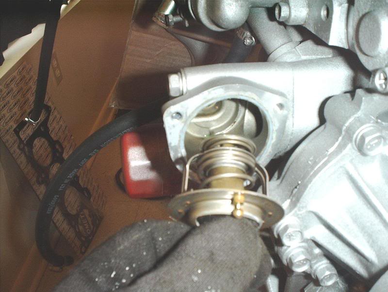
Pull it out.
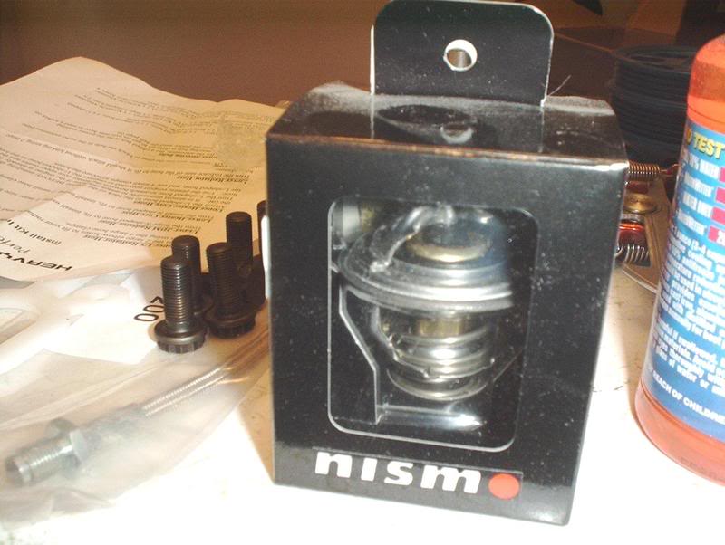
Replacement thermostat.
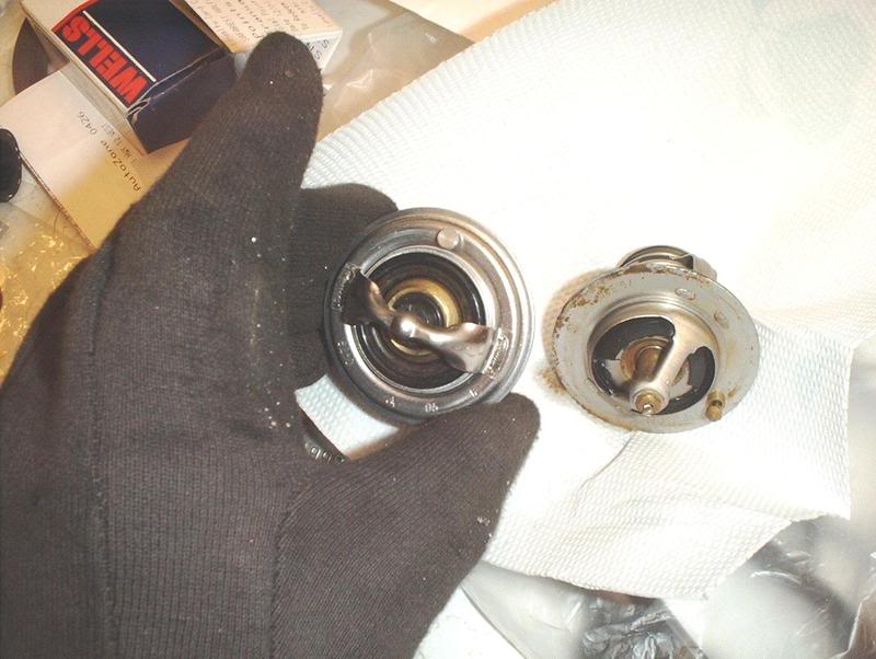
Nismo vs. OEM-if it's anything like the suspension parts then it's a highly overpriced copy of the stock part.
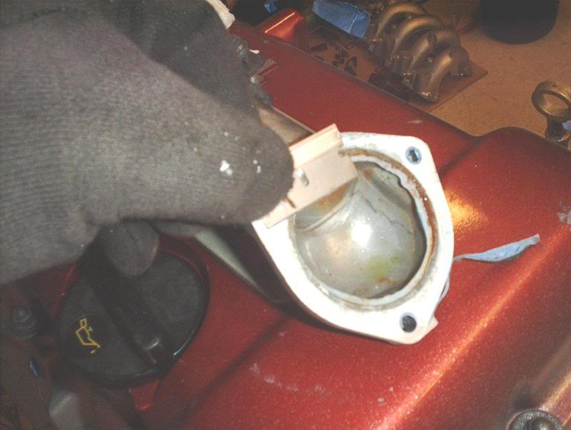
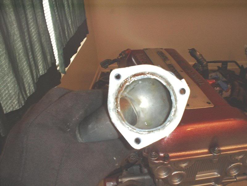
I got a razor blade and removed the leftover gasket on the water outlet and the block.
Place the replacement thermostat in with the jiggle valve upward.
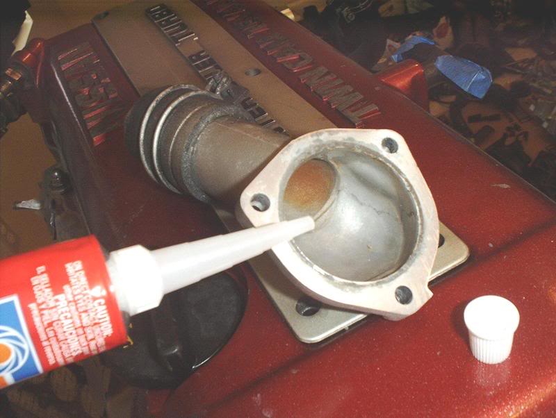
Get some liquid gasket ready and put a 2-3mm bead around the water outlet neck and position it on the block then hand thread the bolts on tight and let it sit for an hour.
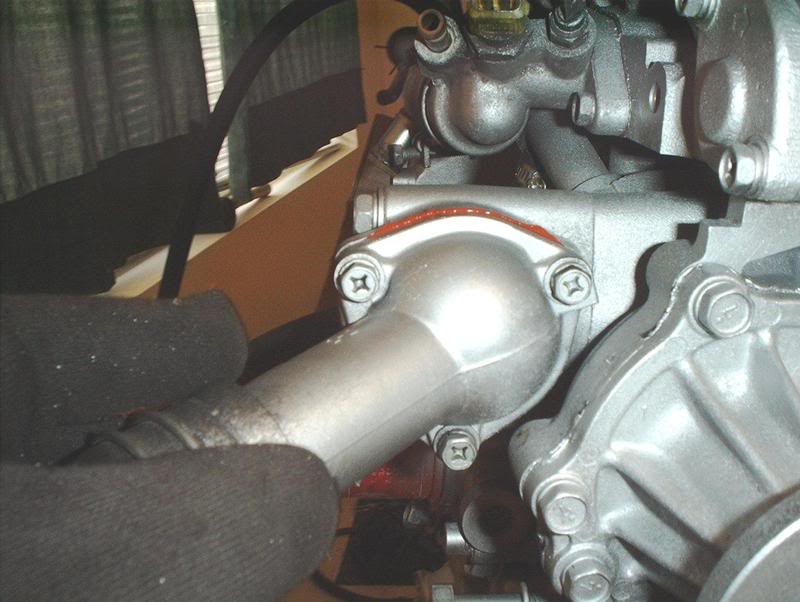
Come back after an hour and then tighten or torque to 2.7-3.7ft-lbs. I didn't use a torque wrench here on account of possibly busting something...it's only 2 to 3ft-lbs. come on.
Tools needed:
Socket wrench
Socket extension
10mm socket
Liquid gasket
Razorblade
Water outlet houses the thermostat.
Use a 10mm socket to remove the water outlet.
After I removed the bolts I had to man-up on the water outlet to bust it loose.
OEM thermostat. Note the position of the jiggle valve.
Pull it out.
Replacement thermostat.
Nismo vs. OEM-if it's anything like the suspension parts then it's a highly overpriced copy of the stock part.
I got a razor blade and removed the leftover gasket on the water outlet and the block.
Place the replacement thermostat in with the jiggle valve upward.
Get some liquid gasket ready and put a 2-3mm bead around the water outlet neck and position it on the block then hand thread the bolts on tight and let it sit for an hour.
Come back after an hour and then tighten or torque to 2.7-3.7ft-lbs. I didn't use a torque wrench here on account of possibly busting something...it's only 2 to 3ft-lbs. come on.
Last edited by positron; May 13, 2008 at 09:44 AM.
Registered User
Joined: Dec 2006
Posts: 434
From: VA
i took a hose and i ran water through the engine to kick out the old water that may of been in the channels. do it from where the heater hoses are. obviously you'll have to do this outside.
you're doing a lot of stuff. i'm not sure if you didi t already, but water pump? replaced? i hope so.
Under drive pullies don't do crap. i bought my greddy's just for the bling factor.
you're doing a lot of stuff. i'm not sure if you didi t already, but water pump? replaced? i hope so.
Under drive pullies don't do crap. i bought my greddy's just for the bling factor.
Thread Starter
Contributing Member
Joined: Sep 2002
Posts: 1,192
From: Starkville, MS.
i took a hose and i ran water through the engine to kick out the old water that may of been in the channels. do it from where the heater hoses are. obviously you'll have to do this outside.
you're doing a lot of stuff. i'm not sure if you didi t already, but water pump? replaced? i hope so.
Under drive pullies don't do crap. i bought my greddy's just for the bling factor.
you're doing a lot of stuff. i'm not sure if you didi t already, but water pump? replaced? i hope so.
Under drive pullies don't do crap. i bought my greddy's just for the bling factor.

Thread Starter
Contributing Member
Joined: Sep 2002
Posts: 1,192
From: Starkville, MS.
Engine/Parts Cleaning
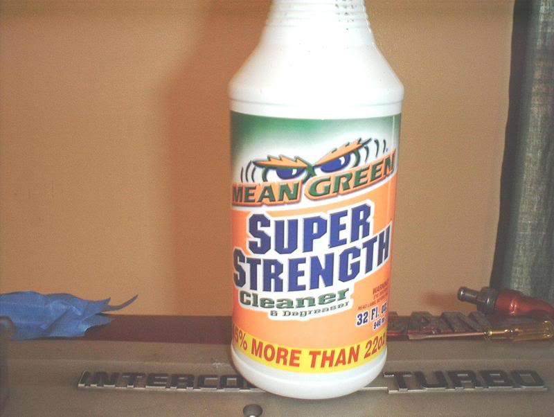
Believe it or not I couldn't find Simple Green at any store here so I got the next best thing....Mean Green.
So far I've gone through about 3 bottles of this stuff and it works wonders on cleaning up a engine and engine parts. Just spray it on watch the grime roll down. For example just check out what it did for my KA P/S pump.
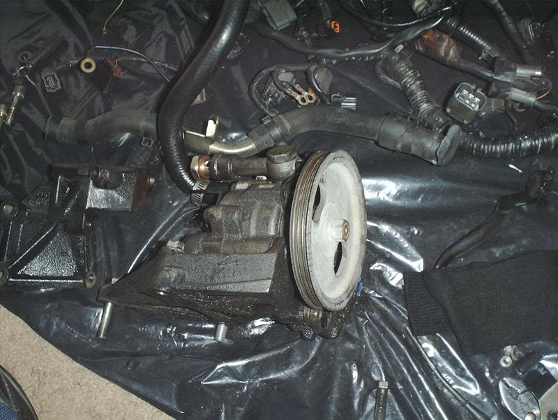
The power steering pumps were the filthiest things I had to clean yet, they were totally covered in crap. I always thought the P/S pumps were black but to my suprise it turned out to be gray underneath all that filth that it was covered with.
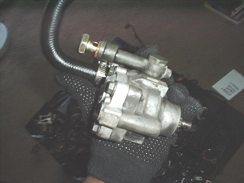
See!
Another little tip for all those grease encrusted nuts, bolts and miscellaneous parts. I just took them, put them in a cup and let them sit in pure Mean Green for a couple of hours and they came out looking almost new except for the scratches.
Quick question, my SR's powersteering pump appears to have two pressure hoses on it, would that be a HICAS pump?
So far I've gone through about 3 bottles of this stuff and it works wonders on cleaning up a engine and engine parts. Just spray it on watch the grime roll down. For example just check out what it did for my KA P/S pump.
The power steering pumps were the filthiest things I had to clean yet, they were totally covered in crap. I always thought the P/S pumps were black but to my suprise it turned out to be gray underneath all that filth that it was covered with.
See!
Another little tip for all those grease encrusted nuts, bolts and miscellaneous parts. I just took them, put them in a cup and let them sit in pure Mean Green for a couple of hours and they came out looking almost new except for the scratches.
Quick question, my SR's powersteering pump appears to have two pressure hoses on it, would that be a HICAS pump?
Thread Starter
Contributing Member
Joined: Sep 2002
Posts: 1,192
From: Starkville, MS.
Aluminum Steering Bushing
I bought this aluminum steering bushing about two years ago, not long after I purchased the car, after being told that it was a simple install. I soon learned that, with the engine in the car, I would have to pull the entire steering column to install this thing. At the time I hadn't started to do anything on my car and I had very little mechanical know-ho so "F" that I said. Since then this bushing has been sitting in a box collecting dust, I always figured that I would be able to install it easier when I did an engine swap, and the motor was out of the car, so the time has finally come.
Aluminum steering bushing.
Tools needed:
Socket wrench
Socket extension
12mm socket
14mm wrench
Prybar
Hammer
Threadlocker
Before I start I have to tell you that I've put a lot of parts on my car and I have to state that this was the most unpleasant install I've done and I've done the rear 300ZX brakes...it wasn't as much of a pain as this was!!!!
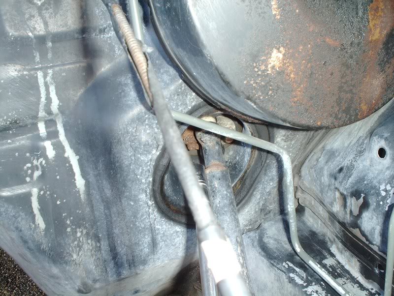
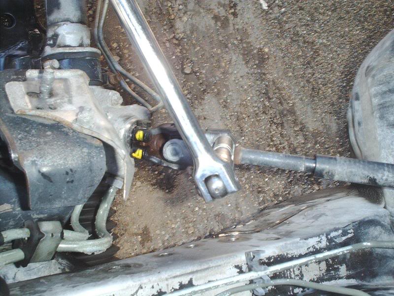
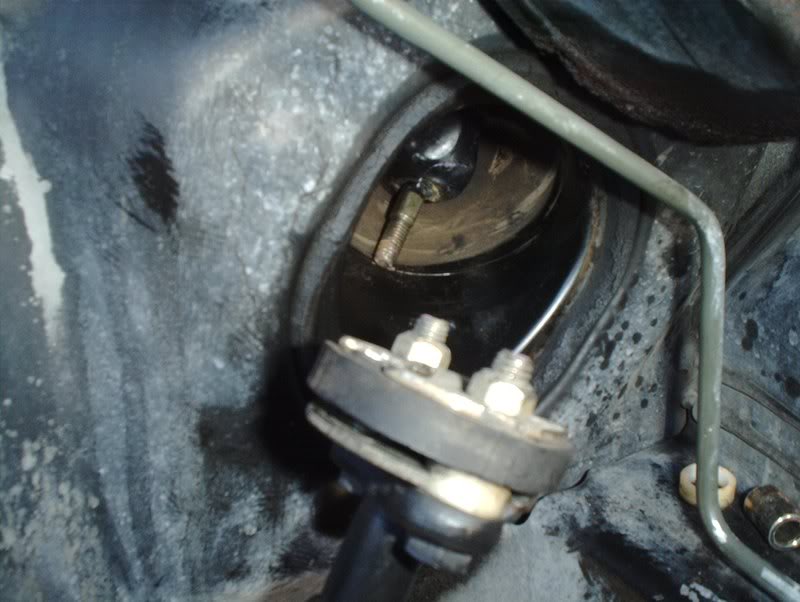
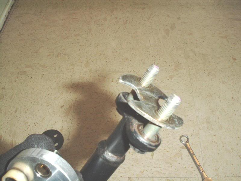
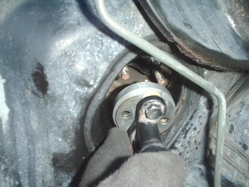
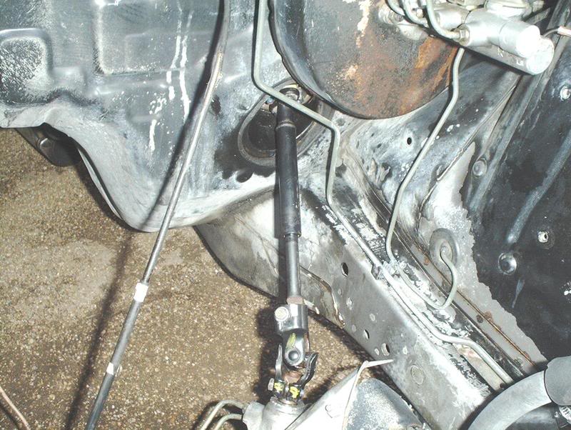
With the engine out of the car you have room to pull just this rod instead of having to pull the entire steering column for the bushing install. It's hard to see but it's there.
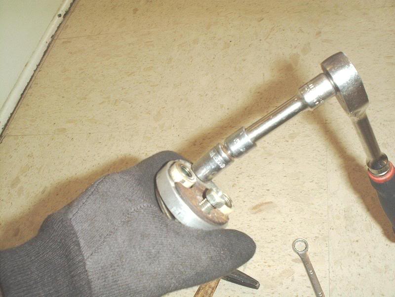
Use a 12mm socket with extension to remove the two nuts off the steering bushing.
I used a breaker bar to bust the two nuts loose on the rod going into the rack and pinion here...
remove the bolt.
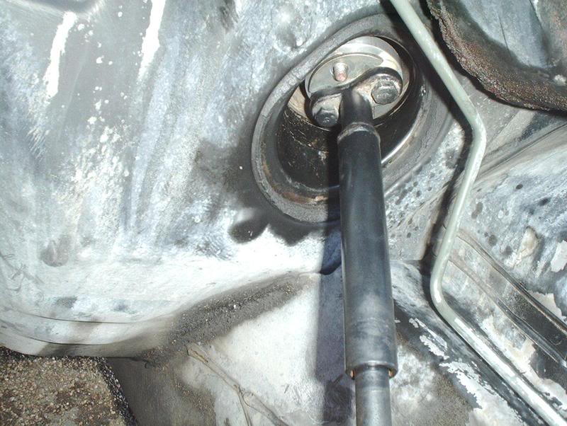
And here...
remove the bolt.
Now this is where I ran into problems, the steering column has splines in it so you should be able to slide part of it down into the universal joint which will give you enough clearance to undo the top portion with the steering bushing where you removed the two nuts earlier, move it to the side and remove it from the car.
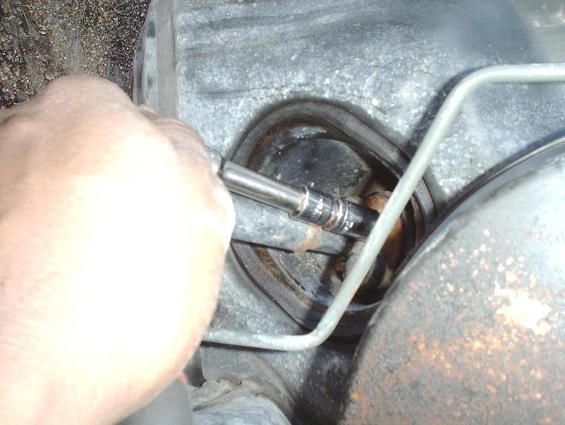
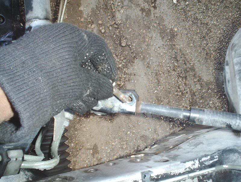
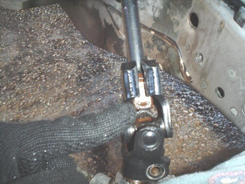
Before I could slide the rod I had to wedge out the universal joint slightly with my prybar.
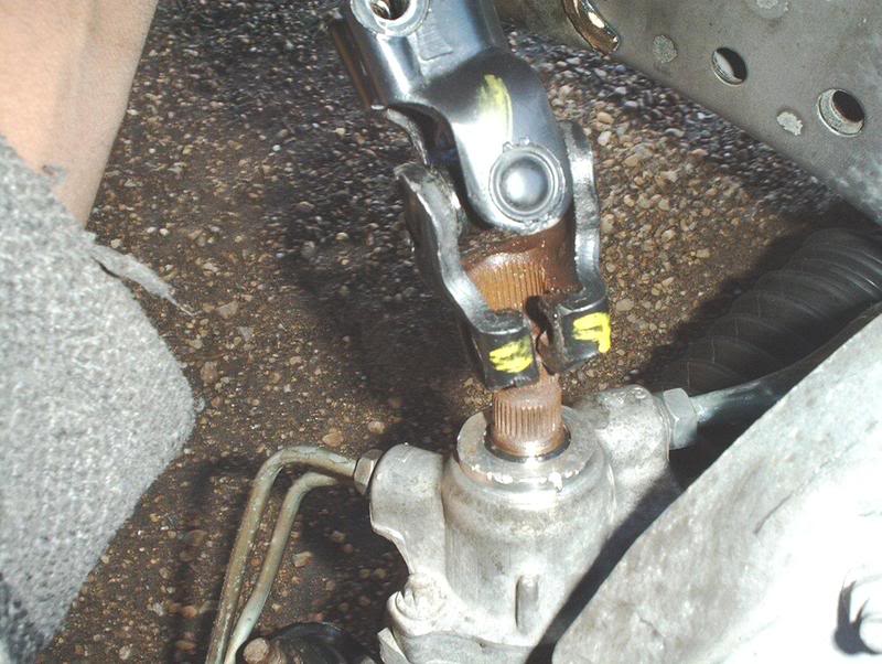
It was rusted so I sprayed some WD-40 on it and continued to use my prybar to wedge out the two connecting points on the universal joint.
After doing that I should have been able to slide the splines on the rod down, move the top of the rod where the steering bushing is to the side, out of that hole leading to the inside of the cabin, and remove it from the universal joint but I didn't have enough clearance. I needed a few more millimeters.
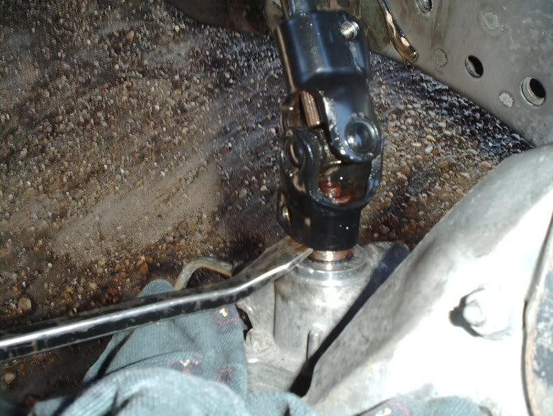
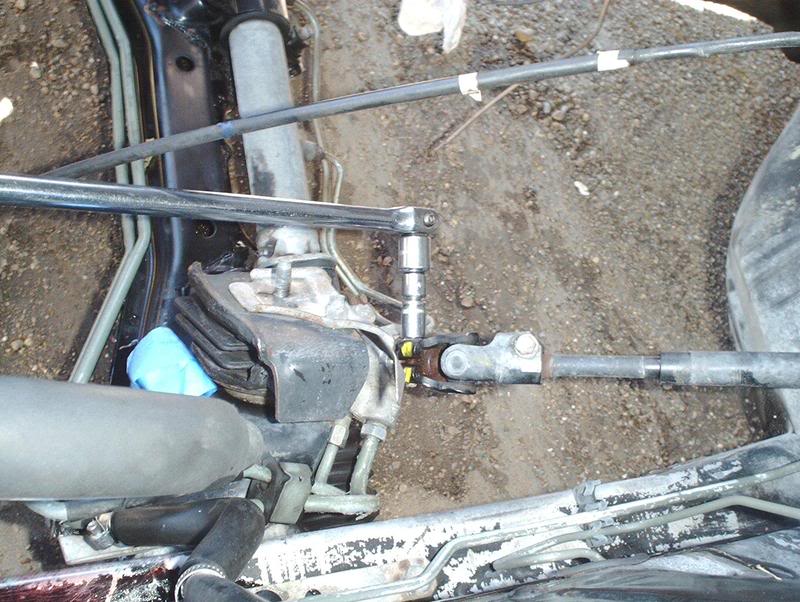
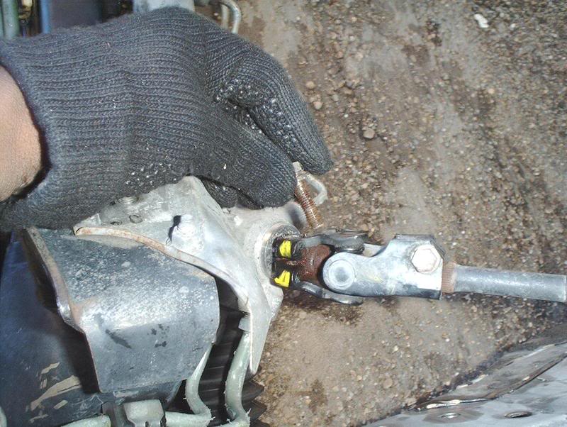
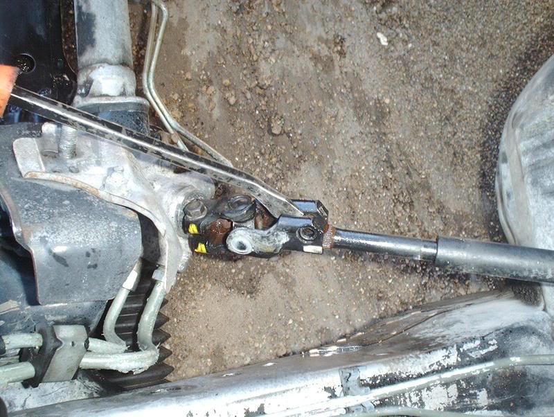
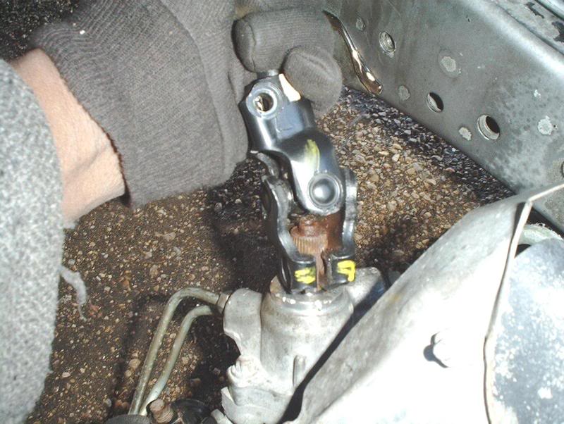
Since I couldn't get it out with that part of the universal joint I tried the lower portion of the universal joint. It has splines also so I wedged it out slightly and used my prybar to move it up...
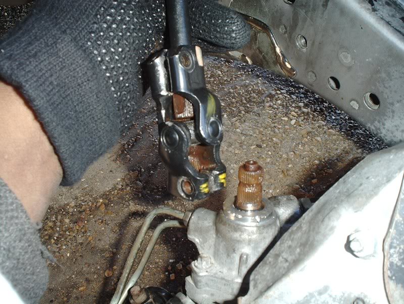
...and off the rack and pinion.
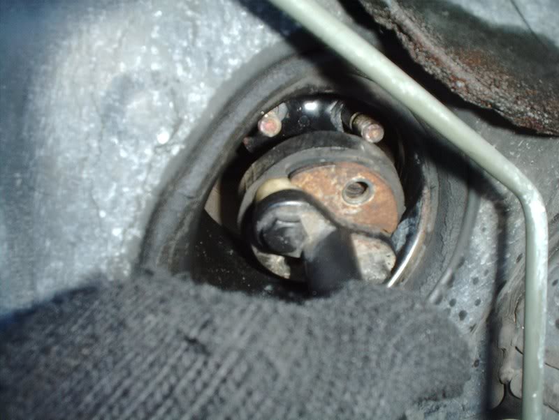
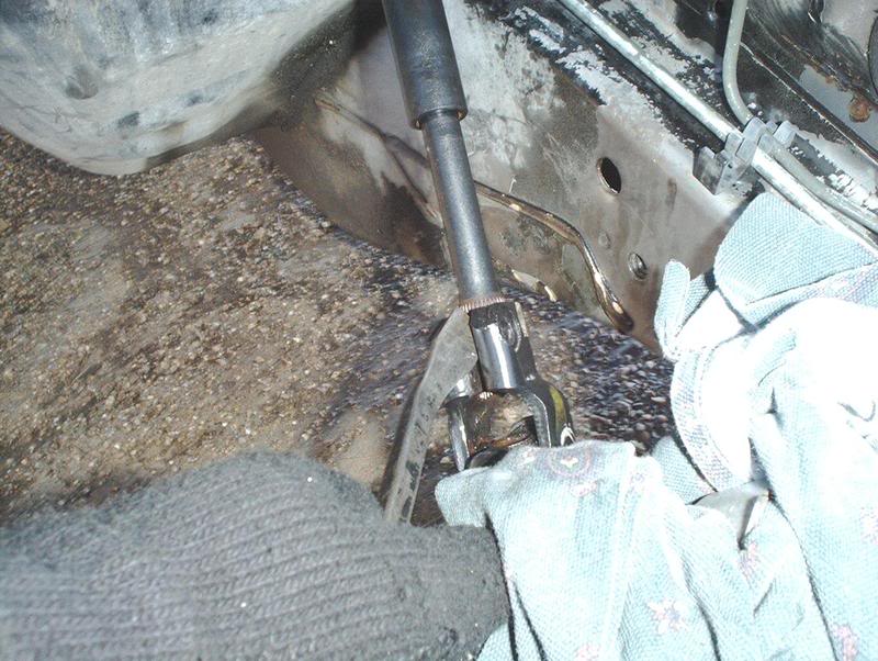
Now you can remove the upper portion of the rod from the steering column.
Here.
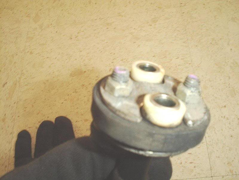
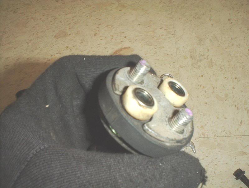
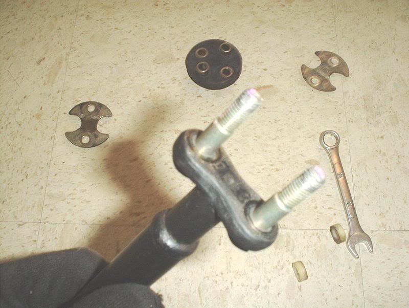
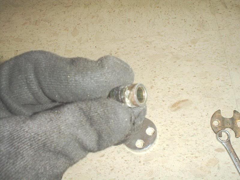
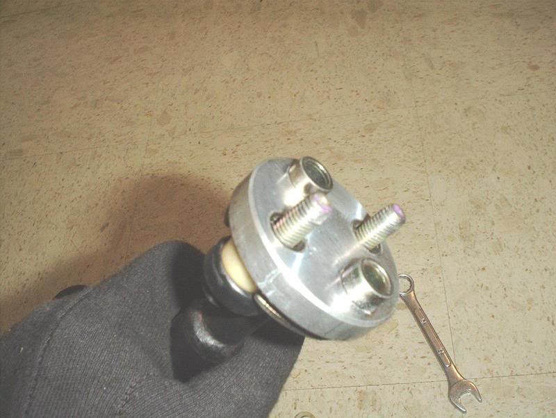
Note the position of the parts on the rod before you break it down so you can install the new bushing and put everything back the same way.
Use a 14mm wrench to help you hold the rod while you use the socket to remove the other two bolts on the steering bushing.
Nuts off.
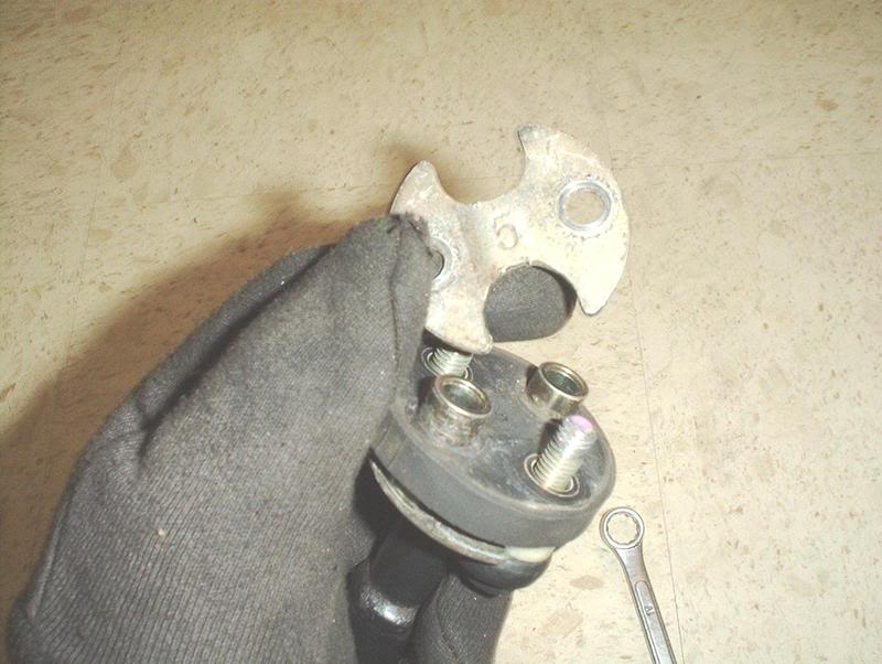
Remove the top washer.
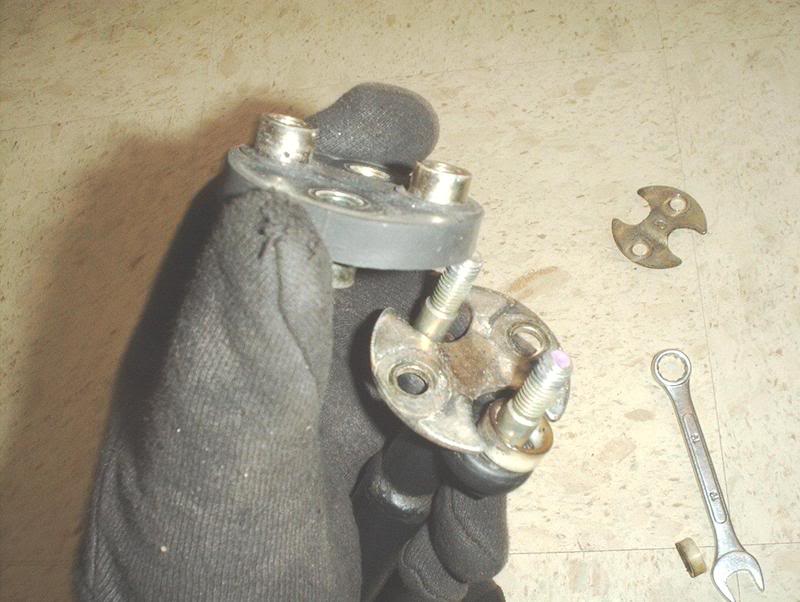
Remove the bushing.
Remove the bottom washer.
Done!
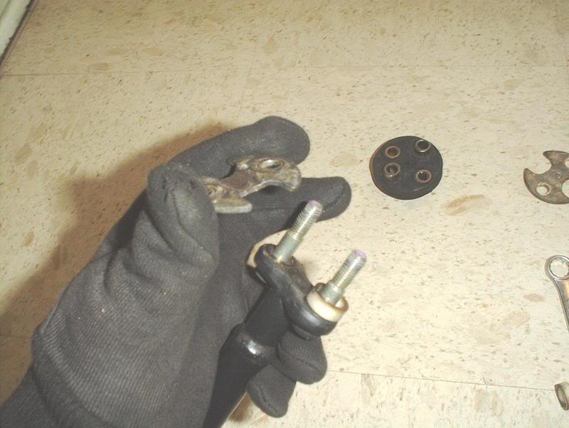
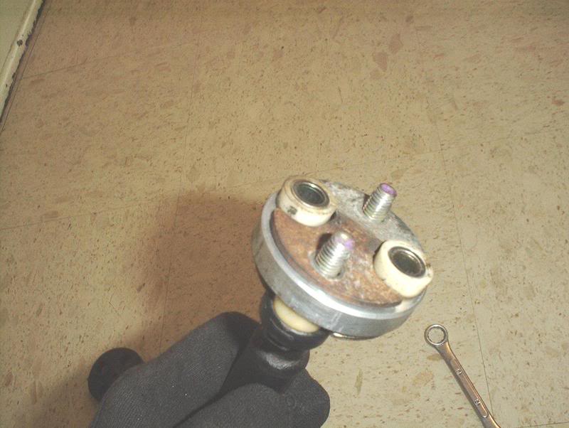
Again, note the position of the metal bushings.
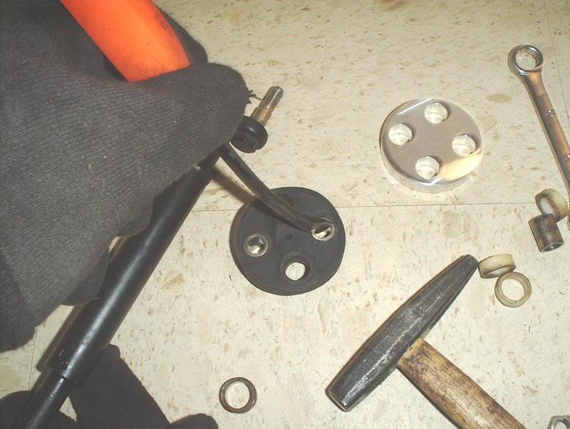
Use a prybar or a screwdriver to pop them out.
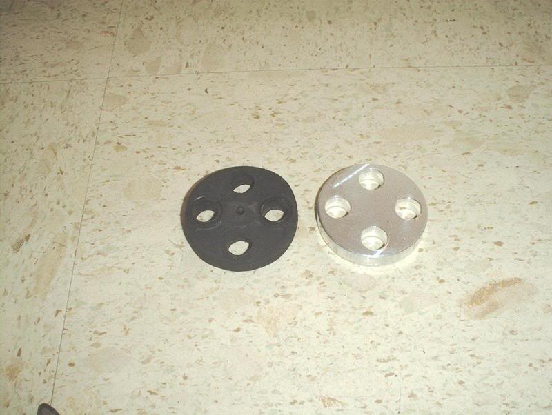
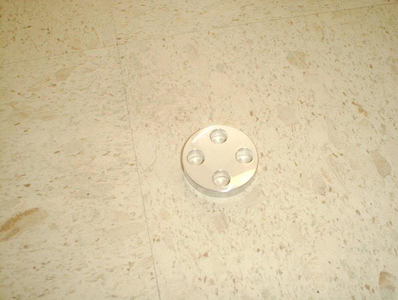
Oem bushing vs. the aluminum steering bushing. The OEM bushing was old and had a lot of flex in it.
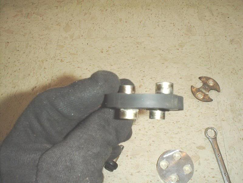
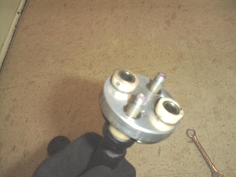
Take the four metal bushings...
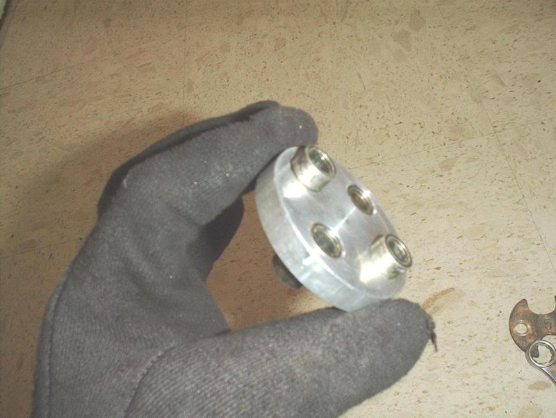
and insert them into the metal steering bushing. You need to alternate the bushings and have two of them flush on one side and the other two flush with the metal steering bushing on the other side.
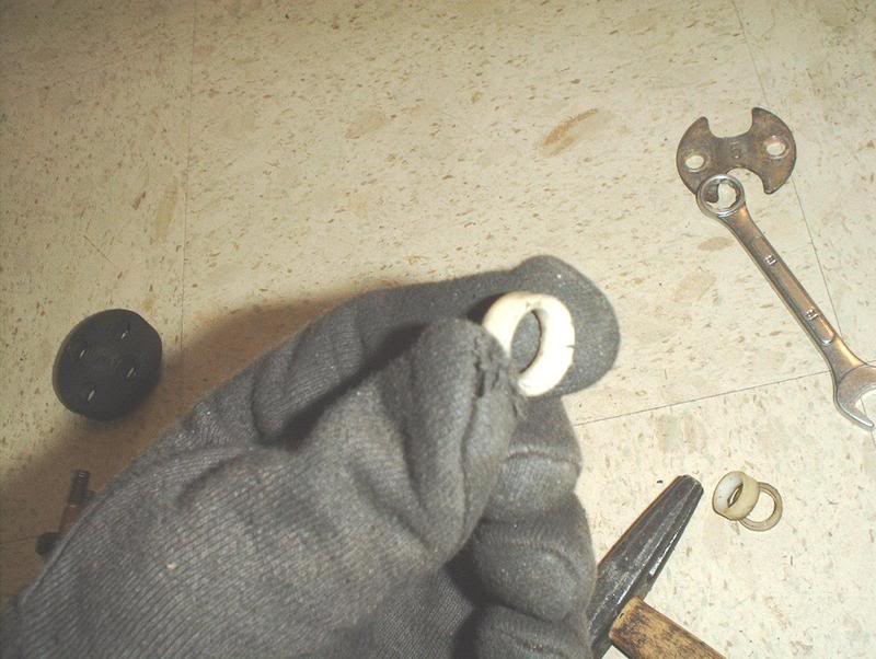
Now take the four plastic washers...
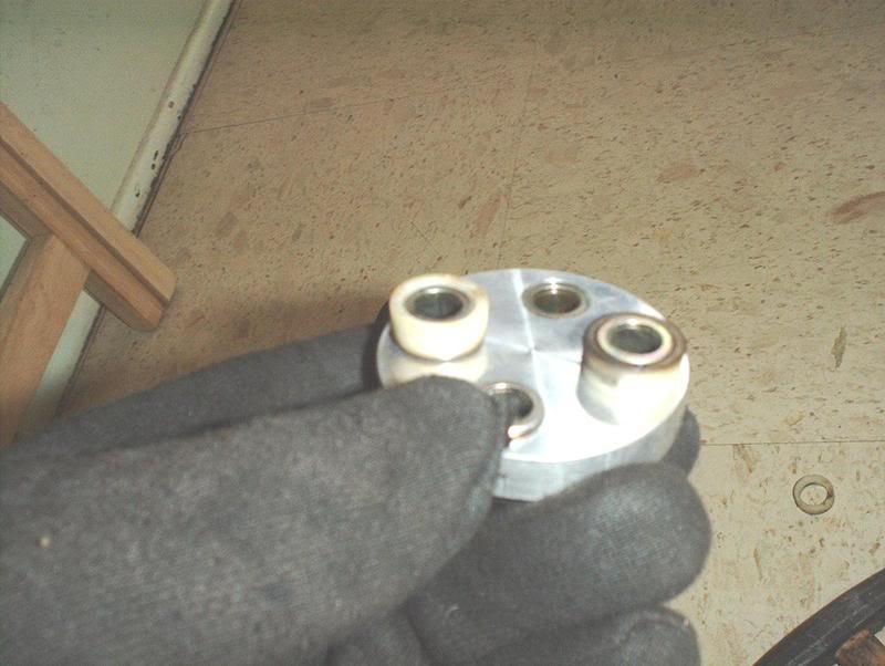
and place them on the four metal bushings and you are ready to reassemble the rod.
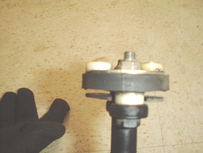
Take the rod and place the bottom washer on.
Place the metal steering bushing on next with the two plastic spacers on the bottom.
Now put the plastic spacers on the top.
Next, the top washer.
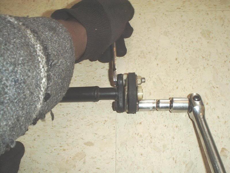
Now you can put the nuts back on and tighten them, sorry I don't have the torque specs on this one...anyone? Don't forget to use the wrench to help you hold the rod while you tighten the nuts.
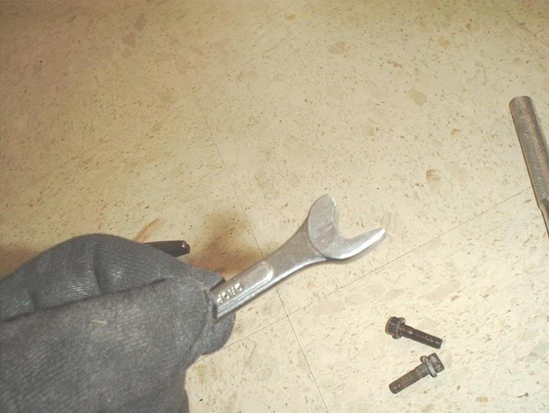
I busted this wrench in the process, gotta track down the Snap-On man Monday!
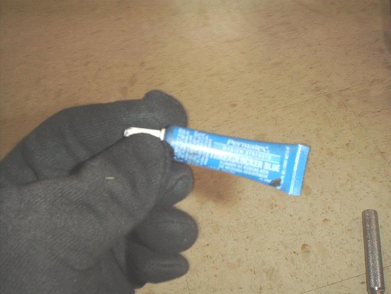
Once you get the nuts tight, use some threadlocker.
Take the rod back to the car and install the upper portion with the steering bushing...
...back onto the steering column and thread the two nuts that you removed at the beginning back on.
Now you can put the bottom portion of the rod back onto the rack and pinion...
Reposition the rod by moving the splines back into the same position that they were in when you started, re-insert the two bolts on the univeral joints and tighten.
The upper universal joint bolt.
The lower universal joint bolt.
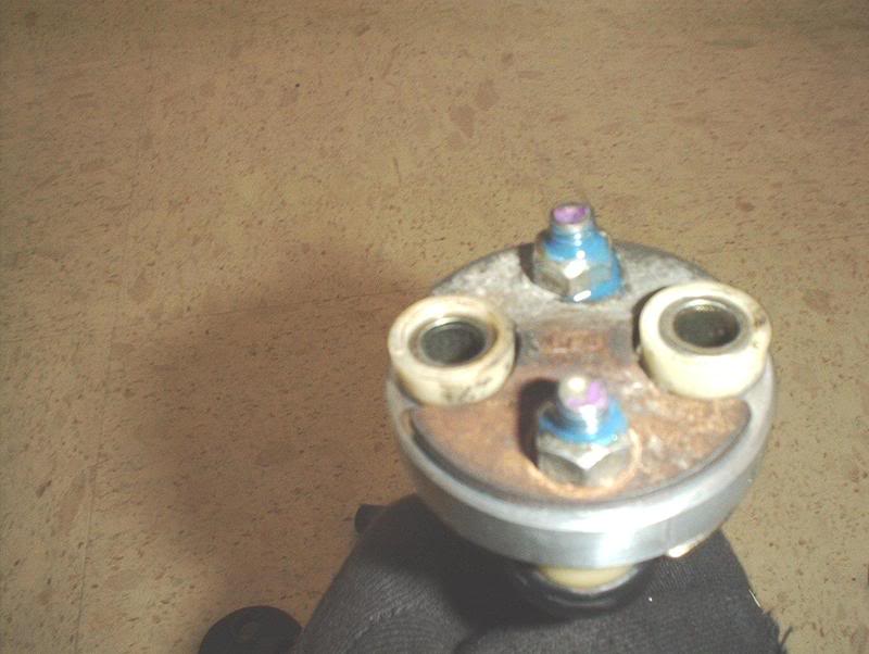
Tighten the two nuts on the upper portion of the rod where the steering bushing is as well and don't forget to use thread locker on all three bolt sections...
...and you are finished!
Aluminum steering bushing.
Tools needed:
Socket wrench
Socket extension
12mm socket
14mm wrench
Prybar
Hammer
Threadlocker
Before I start I have to tell you that I've put a lot of parts on my car and I have to state that this was the most unpleasant install I've done and I've done the rear 300ZX brakes...it wasn't as much of a pain as this was!!!!
With the engine out of the car you have room to pull just this rod instead of having to pull the entire steering column for the bushing install. It's hard to see but it's there.
Use a 12mm socket with extension to remove the two nuts off the steering bushing.
I used a breaker bar to bust the two nuts loose on the rod going into the rack and pinion here...
remove the bolt.
And here...
remove the bolt.
Now this is where I ran into problems, the steering column has splines in it so you should be able to slide part of it down into the universal joint which will give you enough clearance to undo the top portion with the steering bushing where you removed the two nuts earlier, move it to the side and remove it from the car.
Before I could slide the rod I had to wedge out the universal joint slightly with my prybar.
It was rusted so I sprayed some WD-40 on it and continued to use my prybar to wedge out the two connecting points on the universal joint.
After doing that I should have been able to slide the splines on the rod down, move the top of the rod where the steering bushing is to the side, out of that hole leading to the inside of the cabin, and remove it from the universal joint but I didn't have enough clearance. I needed a few more millimeters.
Since I couldn't get it out with that part of the universal joint I tried the lower portion of the universal joint. It has splines also so I wedged it out slightly and used my prybar to move it up...
...and off the rack and pinion.
Now you can remove the upper portion of the rod from the steering column.
Here.
Note the position of the parts on the rod before you break it down so you can install the new bushing and put everything back the same way.
Use a 14mm wrench to help you hold the rod while you use the socket to remove the other two bolts on the steering bushing.
Nuts off.
Remove the top washer.
Remove the bushing.
Remove the bottom washer.
Done!
Again, note the position of the metal bushings.
Use a prybar or a screwdriver to pop them out.
Oem bushing vs. the aluminum steering bushing. The OEM bushing was old and had a lot of flex in it.
Take the four metal bushings...
and insert them into the metal steering bushing. You need to alternate the bushings and have two of them flush on one side and the other two flush with the metal steering bushing on the other side.
Now take the four plastic washers...
and place them on the four metal bushings and you are ready to reassemble the rod.
Take the rod and place the bottom washer on.
Place the metal steering bushing on next with the two plastic spacers on the bottom.
Now put the plastic spacers on the top.
Next, the top washer.
Now you can put the nuts back on and tighten them, sorry I don't have the torque specs on this one...anyone? Don't forget to use the wrench to help you hold the rod while you tighten the nuts.
I busted this wrench in the process, gotta track down the Snap-On man Monday!
Once you get the nuts tight, use some threadlocker.
Take the rod back to the car and install the upper portion with the steering bushing...
...back onto the steering column and thread the two nuts that you removed at the beginning back on.
Now you can put the bottom portion of the rod back onto the rack and pinion...
Reposition the rod by moving the splines back into the same position that they were in when you started, re-insert the two bolts on the univeral joints and tighten.
The upper universal joint bolt.
The lower universal joint bolt.
Tighten the two nuts on the upper portion of the rod where the steering bushing is as well and don't forget to use thread locker on all three bolt sections...
...and you are finished!
Last edited by positron; Jan 12, 2008 at 11:46 PM.
Thread Starter
Contributing Member
Joined: Sep 2002
Posts: 1,192
From: Starkville, MS.
Cleanup Part-2
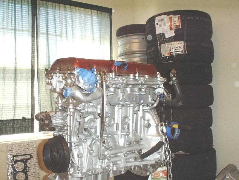
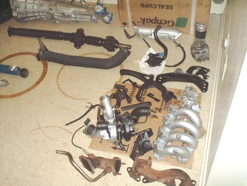
I finally have everything cleaned up and organized so now all I'm doing is waiting on small parts and gaskets so I can start reassembling everything and mounting the parts back onto the block. This thing is actually starting to come together.
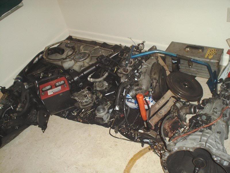
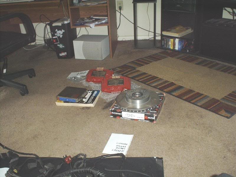
This is the crow's nest that I had before.
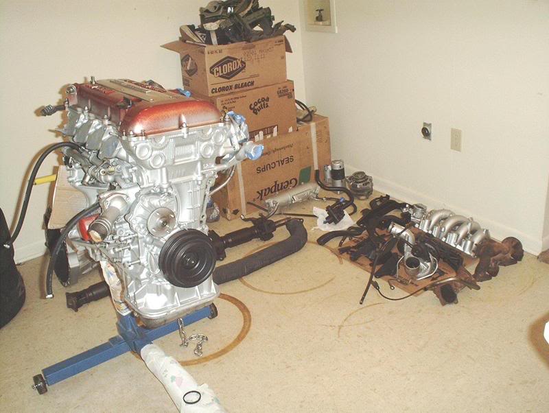
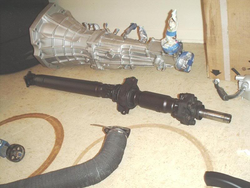
Had a little high heat paint leftover so I used it on the driveshaft. I'm thinking about replacing it with either an aluminum or steel one piece driveshaft though.
This is a project that I was smack right in the middle of completing when I had to drop it and get this swap done!
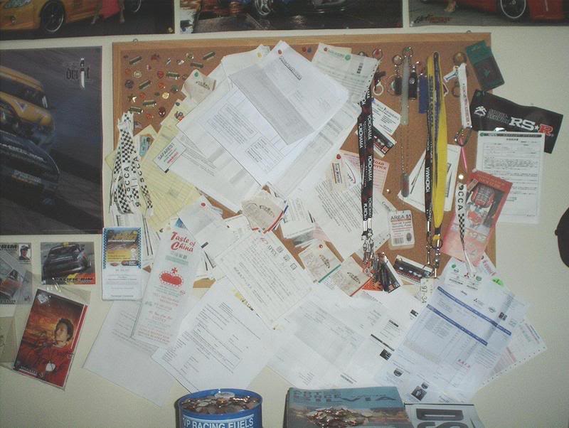
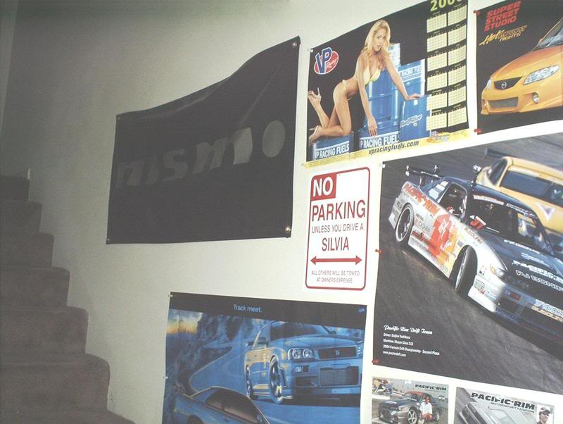
The wall of shame, all the reciepts and bills of lading for the smallest to the largest parts that I've gotten for this freakin' car. Will I ever take them down and add them up....not in this lifetime!
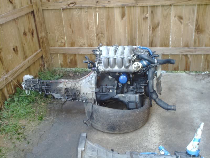
My poor old KA, she served me well.
This is the crow's nest that I had before.
Had a little high heat paint leftover so I used it on the driveshaft. I'm thinking about replacing it with either an aluminum or steel one piece driveshaft though.
This is a project that I was smack right in the middle of completing when I had to drop it and get this swap done!
The wall of shame, all the reciepts and bills of lading for the smallest to the largest parts that I've gotten for this freakin' car. Will I ever take them down and add them up....not in this lifetime!
My poor old KA, she served me well.
Last edited by positron; Jan 13, 2008 at 09:35 AM.
Thread Starter
Contributing Member
Joined: Sep 2002
Posts: 1,192
From: Starkville, MS.
I got most of those banners from Nopi one year. As far as the KA, I'm keeping it around until after the swap just in case I need some parts off it but after that I'm still not sure. I had a friend who was interested in picking it up but I haven't heard from him in awhile so....?
Well if you're going to part it out let me know, i need a few doo-dads from it. I cant imagine how clean that engine bay is going to be when you get that SR in there though. Well, i actually can, and its amazing.
Thread Starter
Contributing Member
Joined: Sep 2002
Posts: 1,192
From: Starkville, MS.

Thread Starter
Contributing Member
Joined: Sep 2002
Posts: 1,192
From: Starkville, MS.
Heater Hose Installation
I put my heater hoses on today, if I did it wrong can someone correct me please?
Tools needed;
Screwdriver
I got a heater hose kit from Heavythrottle but here are the individual part numbers.
L Shape Gates part # 28467
(other cross reference part #'s from Schucks: 80401, M63351, M63812)
S Shape Gates part # 19606
(other cross reference part #'s from Schucks: S63087, 63087)
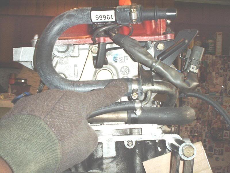
U Shape Gates part # 19666
(other cross reference part # from Schucks: L63297)
Heater hose connector is 5/8" x 3/4"
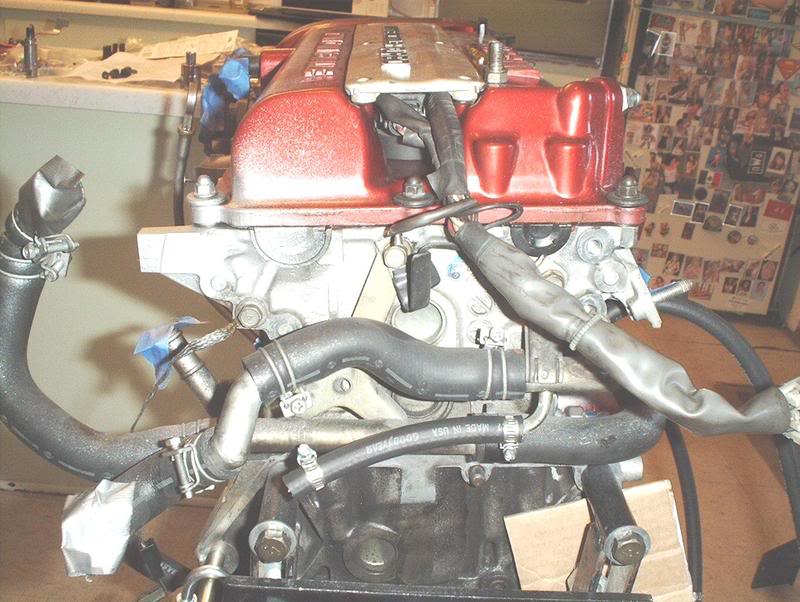
Stock heater hose setup.
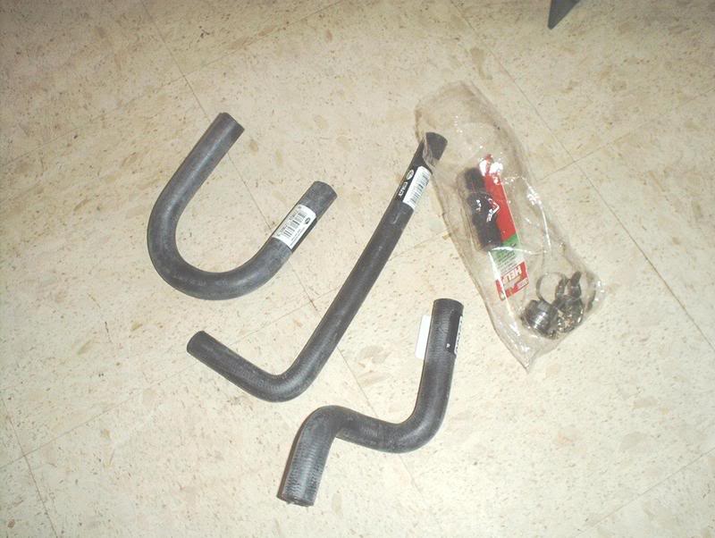
Heater hose kit from HeavyThrottle.
The hoses you have to swap out are the upper heater hose...
and the lower heater hose.
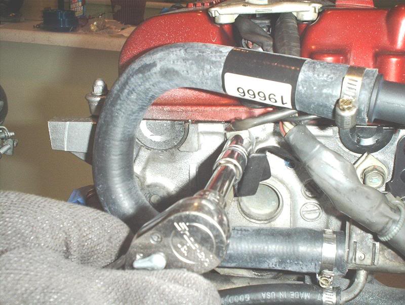
I used a screwdriver to remove the clamp on the upper heater hose.
Remove it.
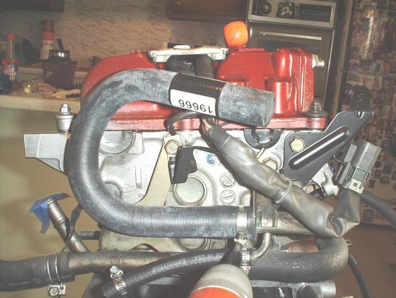
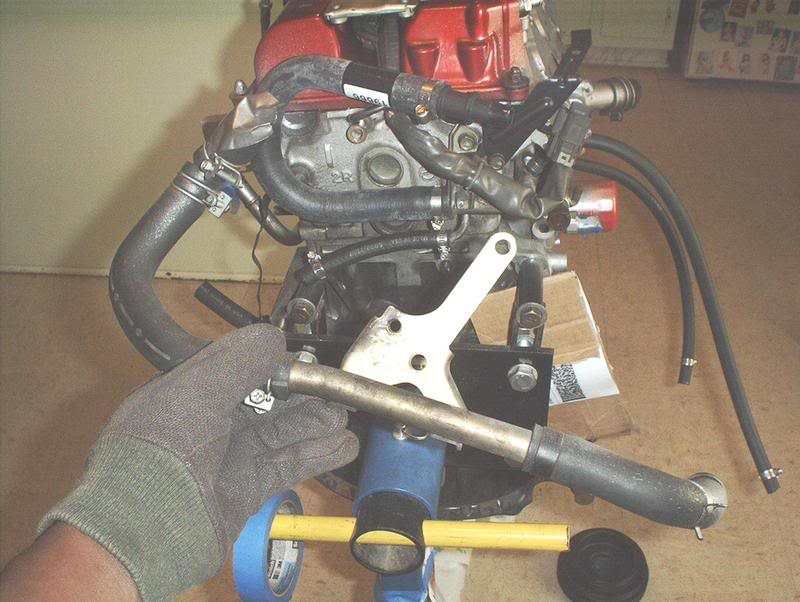
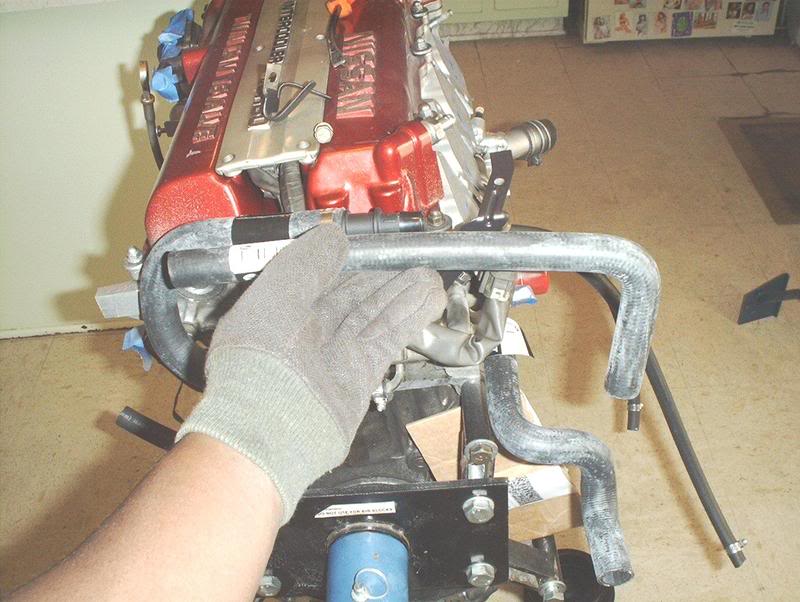
The U-shaped hose goes on the upper heater hose outlet like this.
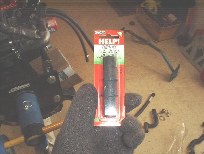
Use this connector to connect the U-shaped hose and the L-shaped hose later.
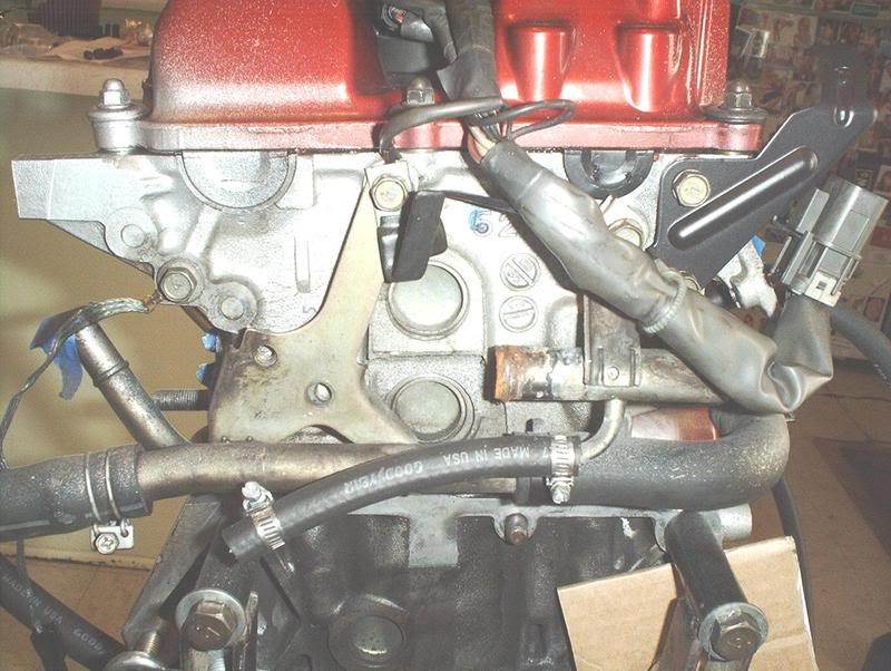
Next, I used a pair of pliers to remove the stock hose from the outlet.
After that you need to remove this bracket.
Now you can remove the hose and connector.
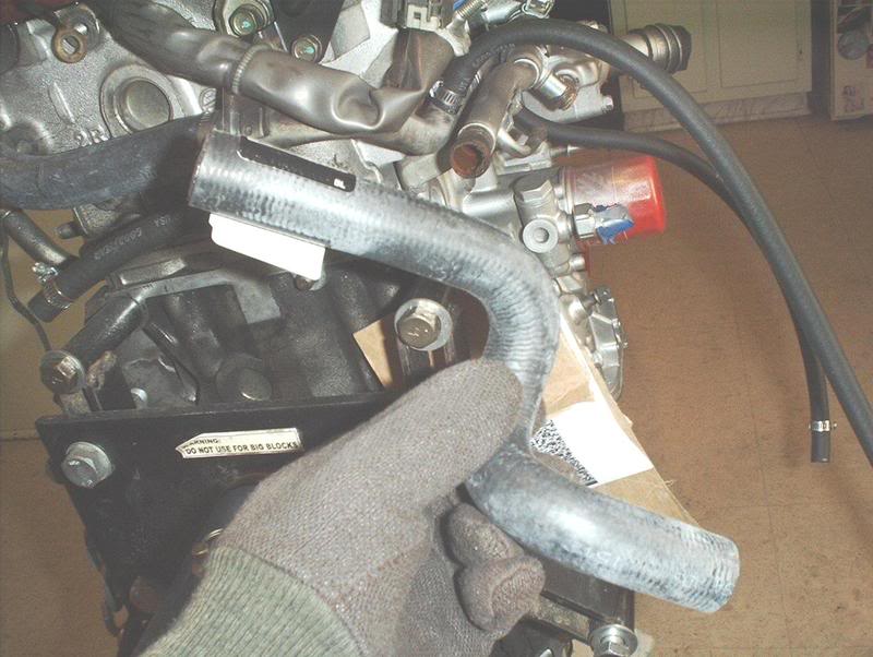
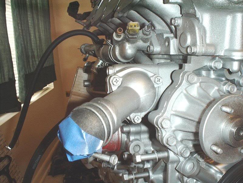
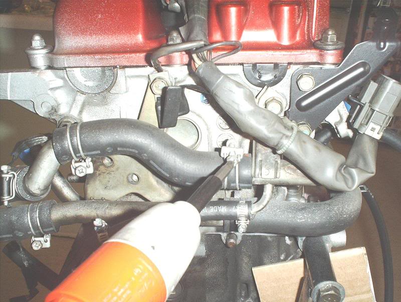
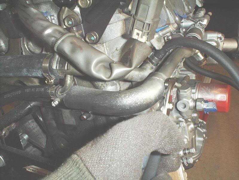
S-shaped heater hose...
installed like this but from what I've read I'll have to remove it when the engine is placed into the car because of firewall clearance.
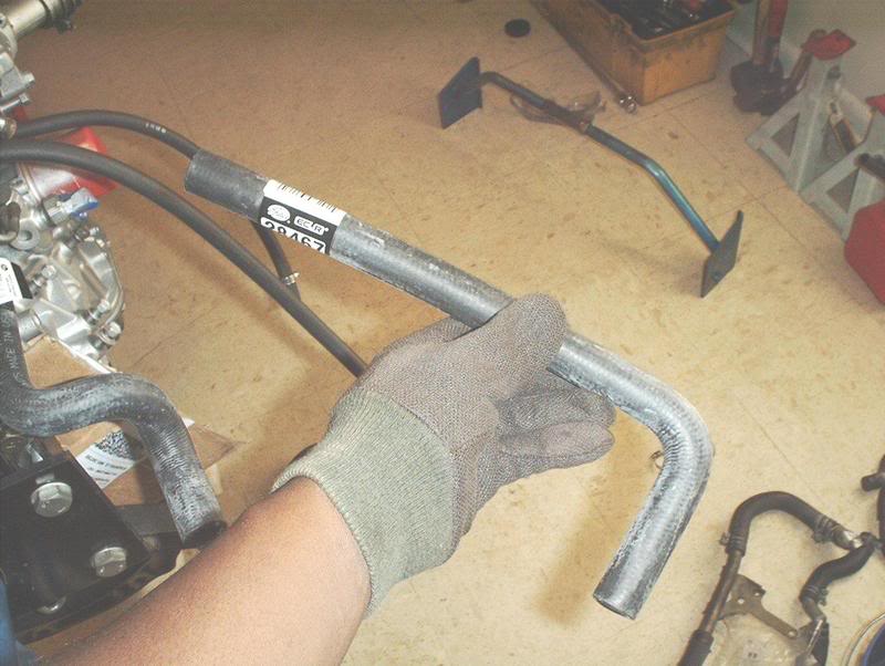
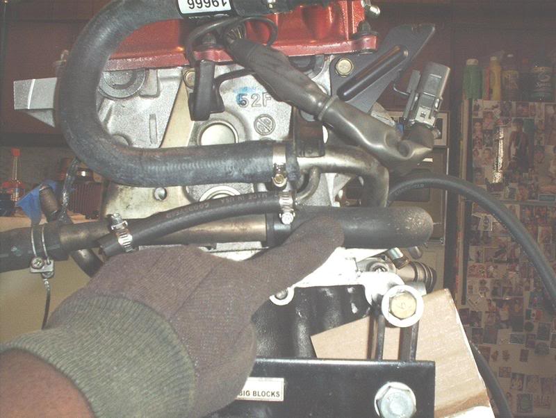
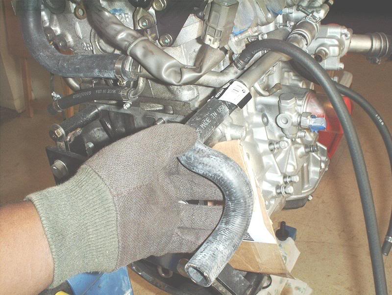
L-shaped heater hose.
The L-shaped hose is connected with the connector to the U-shaped heater hose and is trimed to fit. Someone correct me if I've completed this incorrectly and don't forget about the hose clamps.
Tools needed;
Screwdriver
I got a heater hose kit from Heavythrottle but here are the individual part numbers.
L Shape Gates part # 28467
(other cross reference part #'s from Schucks: 80401, M63351, M63812)
S Shape Gates part # 19606
(other cross reference part #'s from Schucks: S63087, 63087)
U Shape Gates part # 19666
(other cross reference part # from Schucks: L63297)
Heater hose connector is 5/8" x 3/4"
Stock heater hose setup.
Heater hose kit from HeavyThrottle.
The hoses you have to swap out are the upper heater hose...
and the lower heater hose.
I used a screwdriver to remove the clamp on the upper heater hose.
Remove it.
The U-shaped hose goes on the upper heater hose outlet like this.
Use this connector to connect the U-shaped hose and the L-shaped hose later.
Next, I used a pair of pliers to remove the stock hose from the outlet.
After that you need to remove this bracket.
Now you can remove the hose and connector.
S-shaped heater hose...
installed like this but from what I've read I'll have to remove it when the engine is placed into the car because of firewall clearance.
L-shaped heater hose.
The L-shaped hose is connected with the connector to the U-shaped heater hose and is trimed to fit. Someone correct me if I've completed this incorrectly and don't forget about the hose clamps.
Last edited by positron; May 13, 2008 at 09:47 AM.