
My S13 SR20DET Prep

Registered User
Joined: Mar 2008
Posts: 21
From: Fontana, CA
I've never built an sr or any nissan for that matter but when I did a teardown of my engine I did pretty much everything you did. But I didn't have a choice in the matter as I had spun a rod bearing.
So I got a brand new (well used) crank and had it micro polished
new pistons .25 over and had all of the cylinders bored to match those and the whole bottom end hot dipped rather than painted. Then replaced all seals, bearings, etc.
Same with the top end I got the head ported and polished by alaniz technologies, 3 angle valve job.
And it was that piece of mind that the engine would run like an ox that made it worth that money.
To see the money you've put into the engine so far is almost inspiring and looks like a fun time but I would've spent that coin on the insides of the engine first rather than the other amenities.
It's never too late to save up for it since it's not going in anytime soon.
Thread Starter
Contributing Member
Joined: Sep 2002
Posts: 1,192
From: Starkville, MS.
Rant Of The Day!!!
So I send my old valve cover washers to Bonehead Performance for a powdercoating and I get them back today and the Post Office screws me. The package is ripped and I'm missing five of the twelve valve cover washers....WTF!!! They, the Postal Office, include some letter about how sorry they are for the inconvenience but no mention whatsoever about resolving the problem.
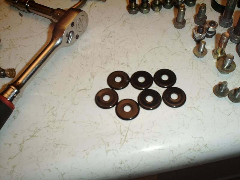
Yea, they screwed me!!! Bonehead Performance did an excellent job powdercoating them by the way!
Yea, they screwed me!!! Bonehead Performance did an excellent job powdercoating them by the way!
Thread Starter
Contributing Member
Joined: Sep 2002
Posts: 1,192
From: Starkville, MS.
Coolant Temp Sensor/Coolant Guage Sensor Replacement
I replaced the coolant temp sensor and guage sensors today.
Tools needed:
12mm wrench
19mm wrench
Teflon tape
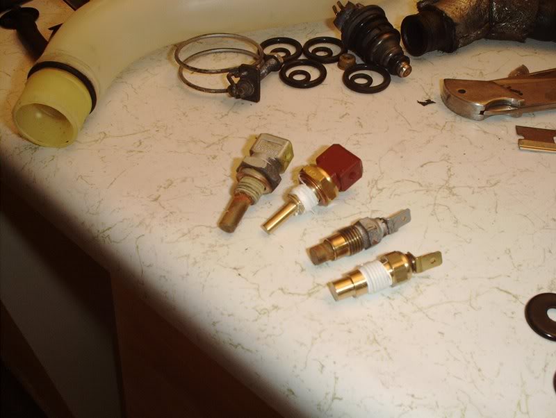
The coolant temp sensor and the coolant guage sensor.
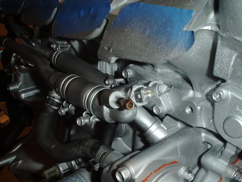
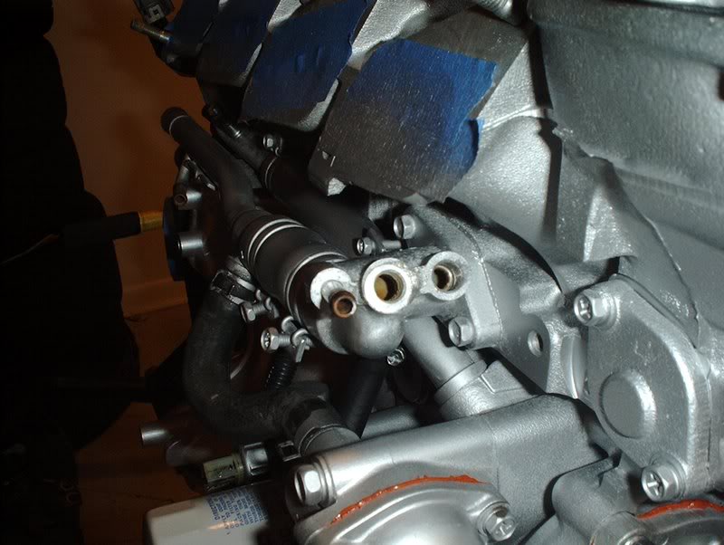
On the KA24DE engine you could get these sensors off without taking off the intake manifold but on the SR the manifold blocks you so it had to come off.

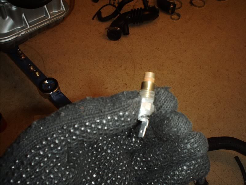
Use a 19mm wrench to remove the coolant temp sensor.
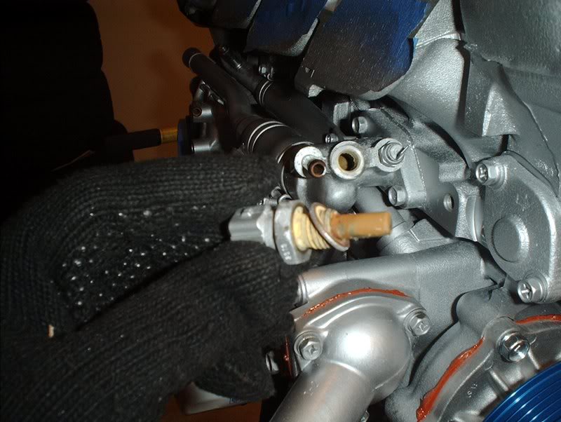
Coolant temperature sensor, this sends the signal to your ECU.
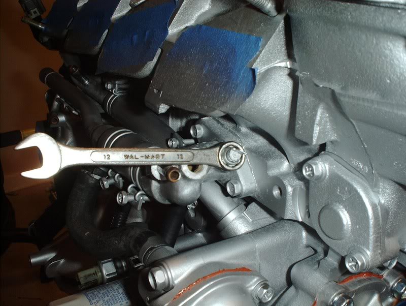
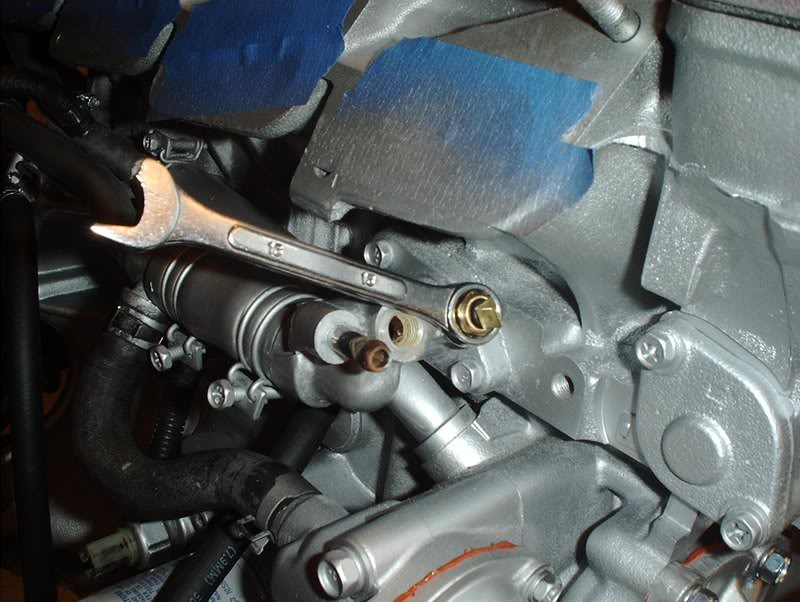
Use a 12mm wrench to remove the coolant guage sensor...yeah I'm rockin' the Wal-Mart wrenches.
Coolant guage sensor, this sends the signal to the temperature guage on your guage cluster.
Put some teflon tape on the threads of the new units and....
it's time to install them.
The new coolant guage sensor.
The new coolant temp sensor.

Finished!
CORRECTION!!! You don't need to remove the intake manifold to replace these sensors, just get deepwell sockets!!!!
Tools needed:
12mm wrench
19mm wrench
Teflon tape
The coolant temp sensor and the coolant guage sensor.
On the KA24DE engine you could get these sensors off without taking off the intake manifold but on the SR the manifold blocks you so it had to come off.
Use a 19mm wrench to remove the coolant temp sensor.
Coolant temperature sensor, this sends the signal to your ECU.
Use a 12mm wrench to remove the coolant guage sensor...yeah I'm rockin' the Wal-Mart wrenches.
Coolant guage sensor, this sends the signal to the temperature guage on your guage cluster.
Put some teflon tape on the threads of the new units and....
it's time to install them.
The new coolant guage sensor.
The new coolant temp sensor.
Finished!
CORRECTION!!! You don't need to remove the intake manifold to replace these sensors, just get deepwell sockets!!!!
Last edited by positron; Mar 20, 2008 at 11:18 PM.
Thread Starter
Contributing Member
Joined: Sep 2002
Posts: 1,192
From: Starkville, MS.
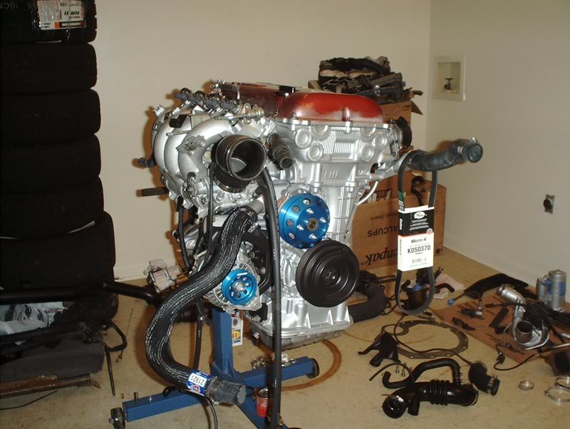
Alternator/Aftermarket Pulley Install
I finally got around to putting my alternator back on.
Tools needed:
Socket wrench
Socket extension
12mm socket
14mm socket
23mm socket
Oil filter pliers
Breaker bar
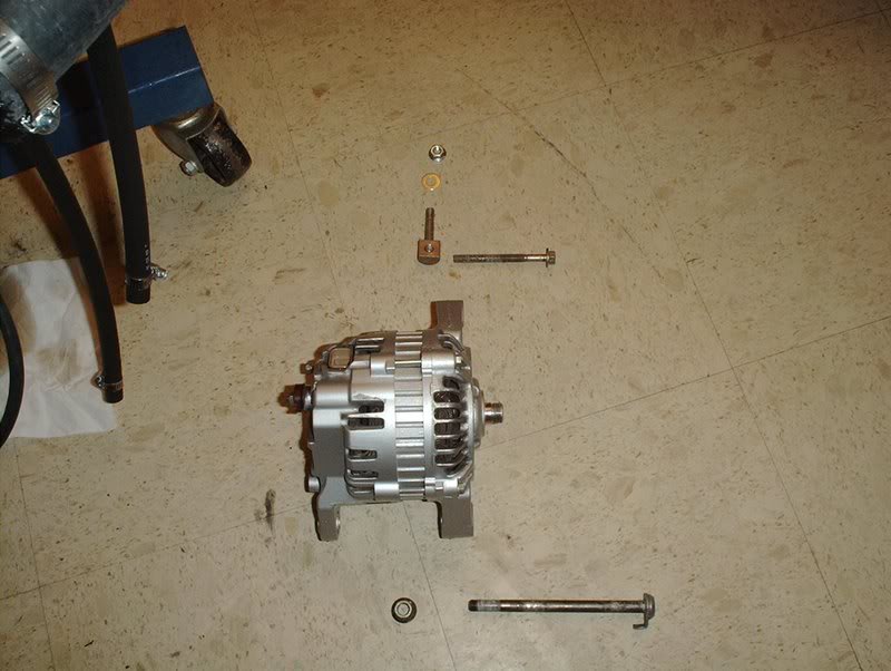
I got a set of aftermarket pullies and needed to put the alternator pulley on before I installed the alternator back on the block. The problem here is that the pulley spins when you touch it so I needed to find a way to stop it from spinning so I could take the alternator pulley nut off.
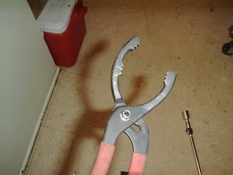
I played around with a few ideas and came up with this one. I got my oil filter pliers out.
The pulley is close to the same size in width as a oil filter so I put the alternator on the ground, placed the oil filter pliers around it with my left foot on the handles to hold it and used the 23mm socket and breaker bar to bust the alternator nut loose.
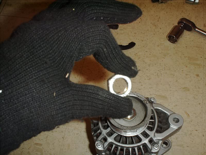
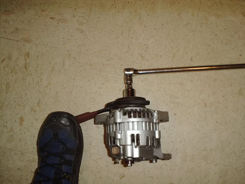
Alternator nut.
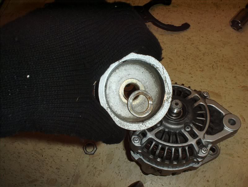
The OEM pulley and washer.
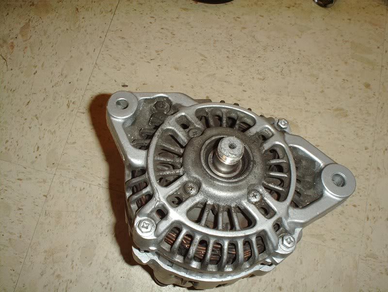
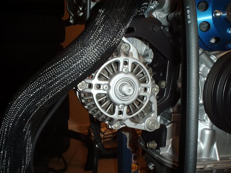
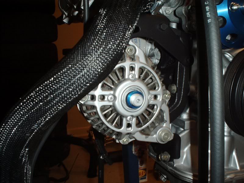
Alternator.
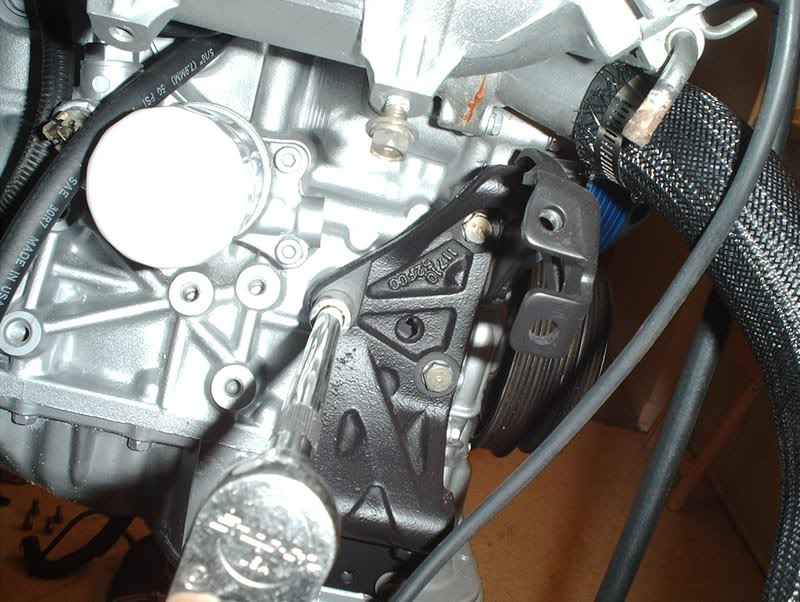
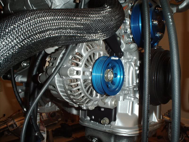
Take the alternator bracket and use a 14mm socket with an extension to bolt the three alternator bolts into the block here.
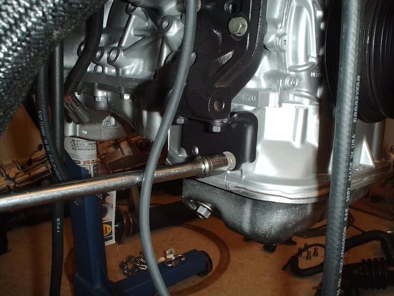
There's two 12mm bolts on the bottom of the alternator bracket here.
The alternator with bolts both top and bottom.
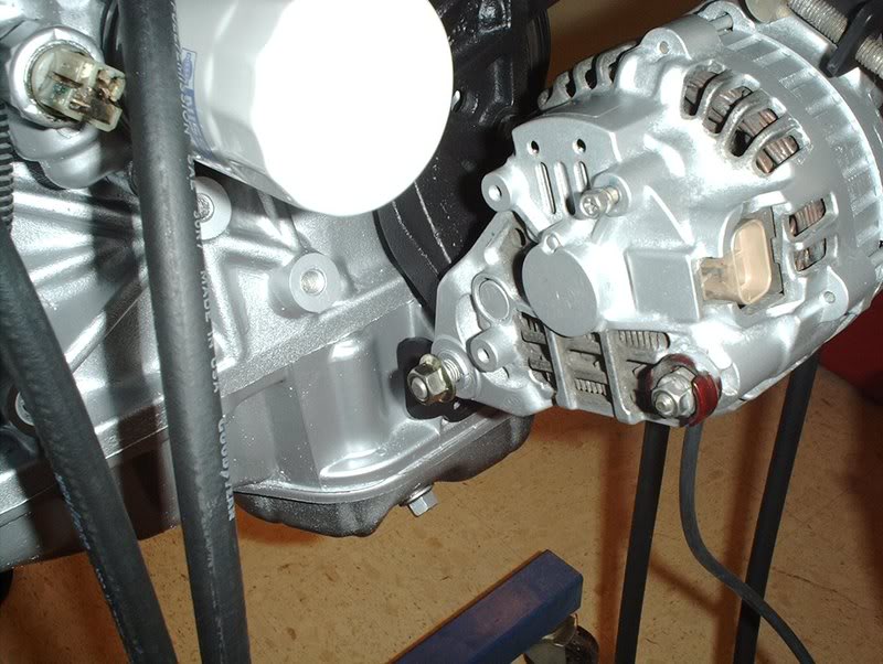
The extra long bolt on the bottom of the picture above goes through the bottom of the alternator and bracket. The other bolts are for your ground wires of course.
The bolts on the top of the pic from earlier go through the top of the alternator and bracket in a L formation.
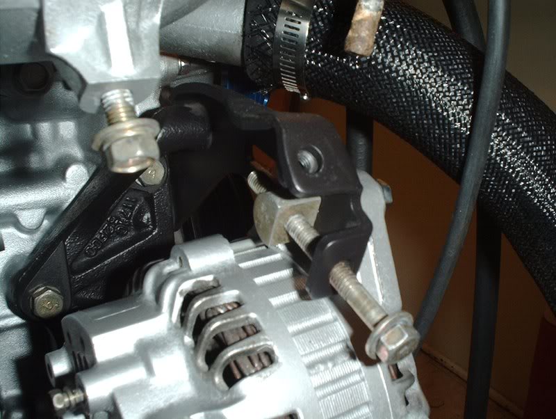
I installed and torqued the new pulley back on the alternator in the same fashion that I took off the OEM pulley so I just took pics of the uninstalled pulley just to show how it goes back on for reference.
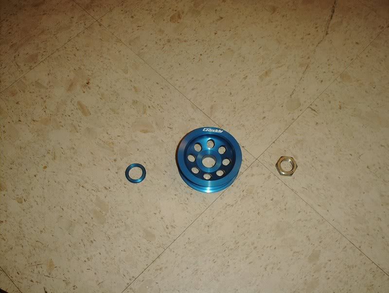
Greddy alternator pulley with spacer and alternator nut.
Alternator.
Unlike the OEM pulley that had a washer or spacer right under the alternator nut, the Greddy pulley comes with a spacer that goes on first. I read that it's there to keep the pulley from bottoming out or something.
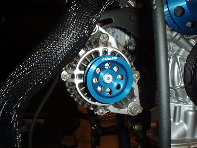
The pulley goes on next.
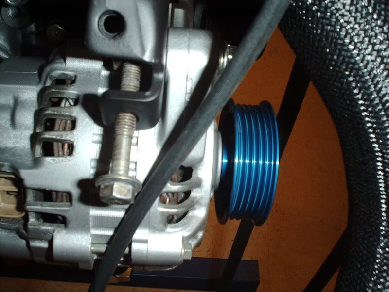
You can see the spacer here, I haven't torqued them down yet though.
Finally the alternator nut, I couldn't find torque specs for this so anyone????
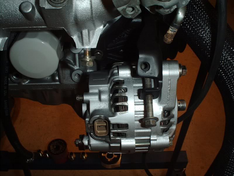
Finished!
Tools needed:
Socket wrench
Socket extension
12mm socket
14mm socket
23mm socket
Oil filter pliers
Breaker bar
I got a set of aftermarket pullies and needed to put the alternator pulley on before I installed the alternator back on the block. The problem here is that the pulley spins when you touch it so I needed to find a way to stop it from spinning so I could take the alternator pulley nut off.
I played around with a few ideas and came up with this one. I got my oil filter pliers out.
The pulley is close to the same size in width as a oil filter so I put the alternator on the ground, placed the oil filter pliers around it with my left foot on the handles to hold it and used the 23mm socket and breaker bar to bust the alternator nut loose.
Alternator nut.
The OEM pulley and washer.
Alternator.
Take the alternator bracket and use a 14mm socket with an extension to bolt the three alternator bolts into the block here.
There's two 12mm bolts on the bottom of the alternator bracket here.
The alternator with bolts both top and bottom.
The extra long bolt on the bottom of the picture above goes through the bottom of the alternator and bracket. The other bolts are for your ground wires of course.
The bolts on the top of the pic from earlier go through the top of the alternator and bracket in a L formation.
I installed and torqued the new pulley back on the alternator in the same fashion that I took off the OEM pulley so I just took pics of the uninstalled pulley just to show how it goes back on for reference.
Greddy alternator pulley with spacer and alternator nut.
Alternator.
Unlike the OEM pulley that had a washer or spacer right under the alternator nut, the Greddy pulley comes with a spacer that goes on first. I read that it's there to keep the pulley from bottoming out or something.
The pulley goes on next.
You can see the spacer here, I haven't torqued them down yet though.
Finally the alternator nut, I couldn't find torque specs for this so anyone????
Finished!
Last edited by positron; Mar 20, 2008 at 07:17 AM.
Thread Starter
Contributing Member
Joined: Sep 2002
Posts: 1,192
From: Starkville, MS.
Hose Install Continued....
I finally found out where the loose hoses I had for the intake manifold go.
Tools needed:
Hose
Hose clamps
Flathead screwdriver
Knife
For sometime I couldn't figure or find out where the hoses for the coolant line, water line, IACV and throttlebody go but now I know thanks to some help from the forum.
It was mainly these two off the coolant and water lines...
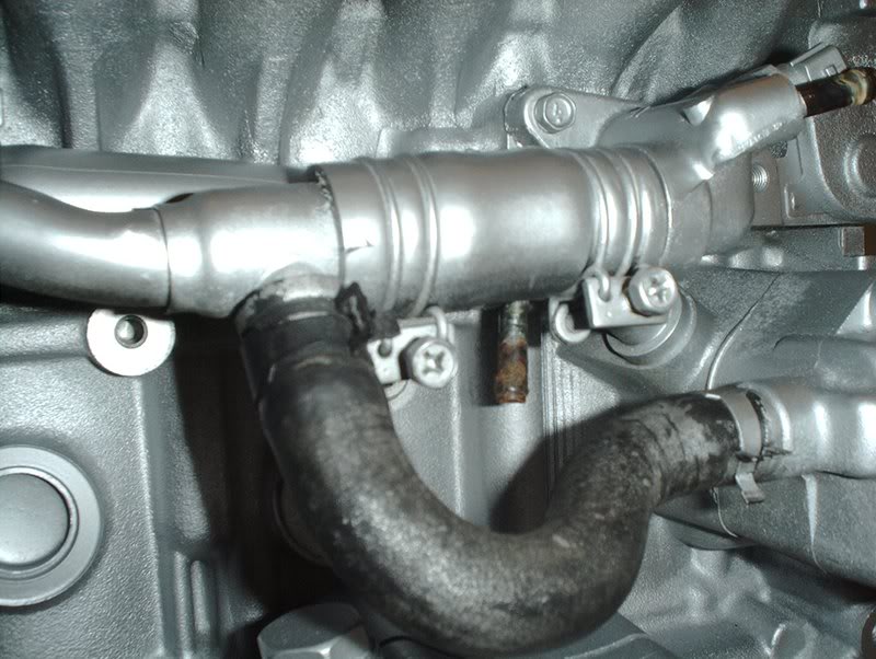
and this port off the water line.
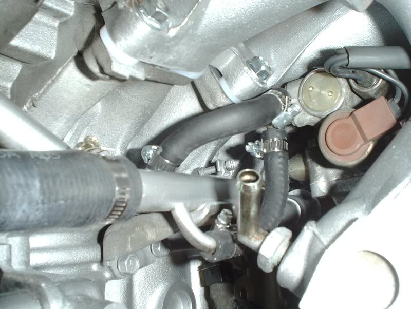
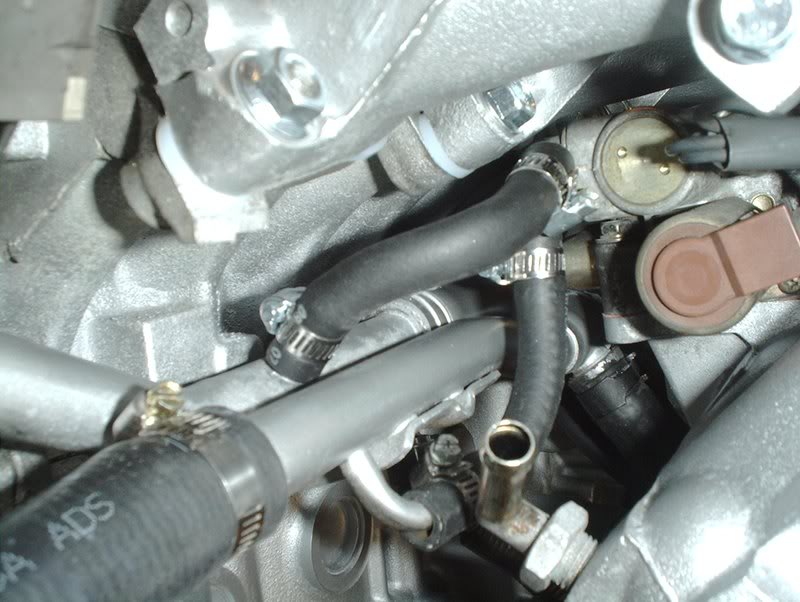
I started with the port coming off the water line.
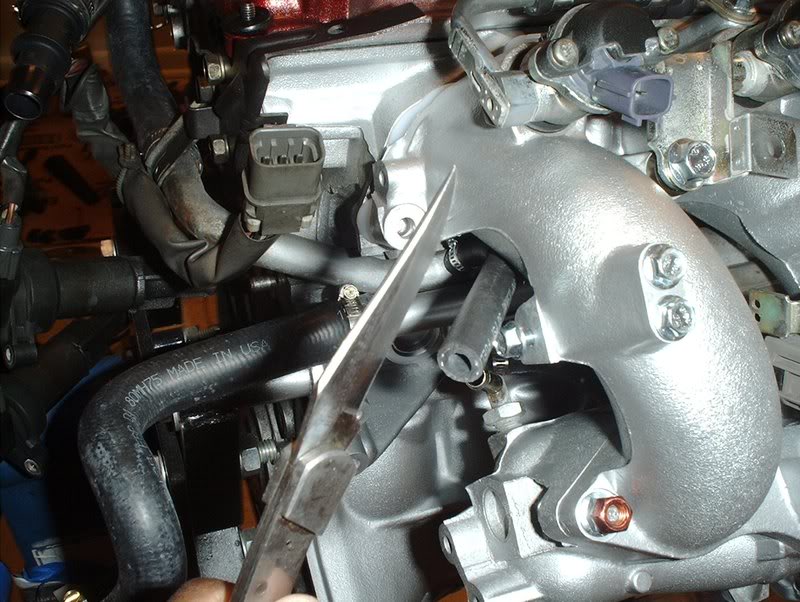
Cut the hose and it connects to the small port on the back of the IACV that points straight down....
like so. Somebody who's done this tell me if this is okay. I didn't want to cut the hose too short to keep it kink free.
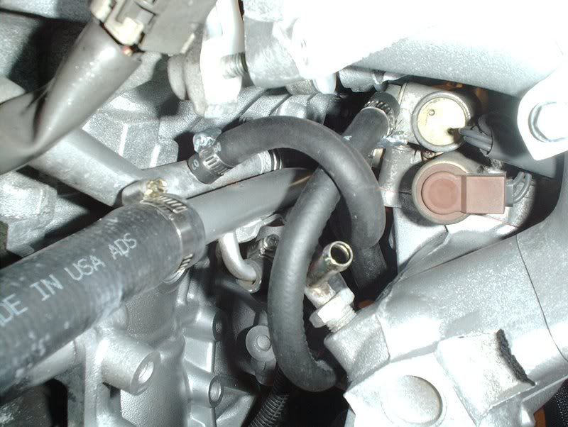
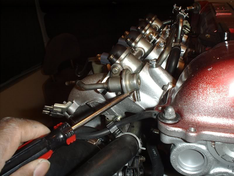
The port coming off the coolant line goes to the other small port on the back of the IACV that points off to the side.
In order to keep this kink free as well I let it loop around slightly like so...
until it connects.
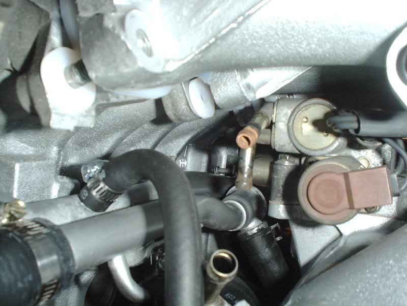
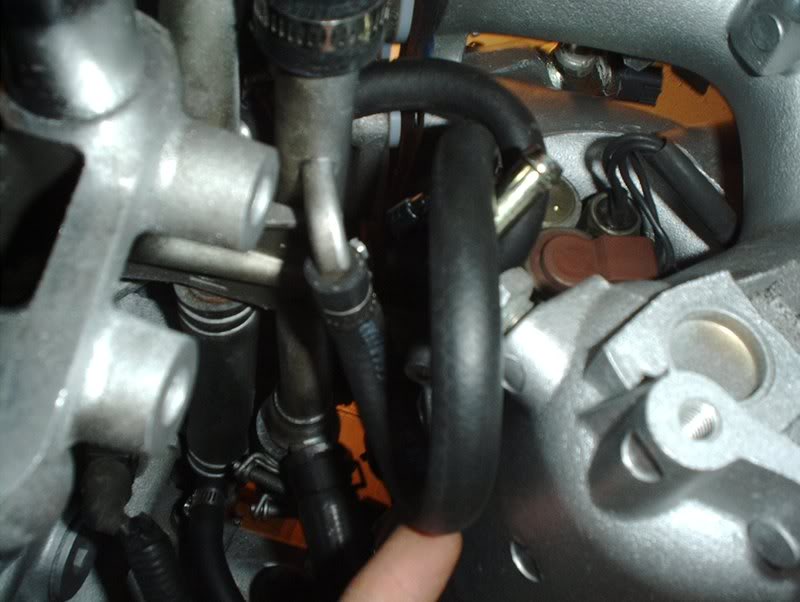
Next there was this one on the water line towards the sensor housing.
It connects to the port on the bottom left of the throttlebody, you know the one that points downward.
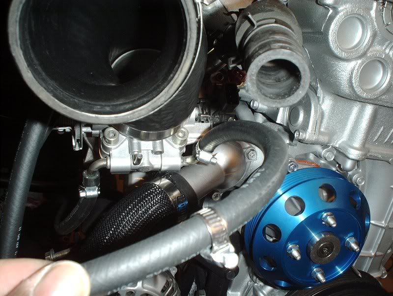
Then there is this one on the bottom right of the throttlebody.
It connects here to the port on the sensor housing...
like so.
And so.
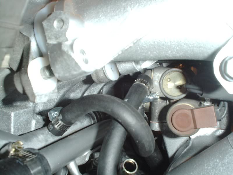
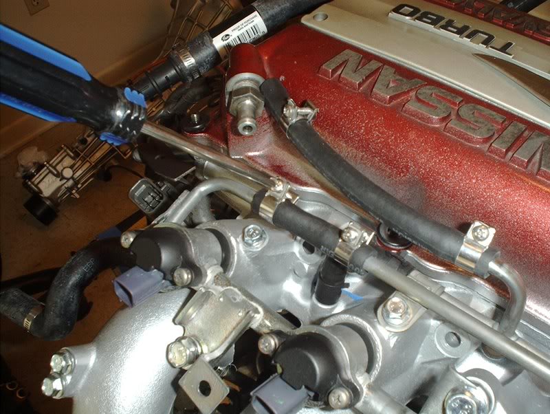
Finally there's the smaller hose that goes from the port on the bottom of the fuel regulator here...
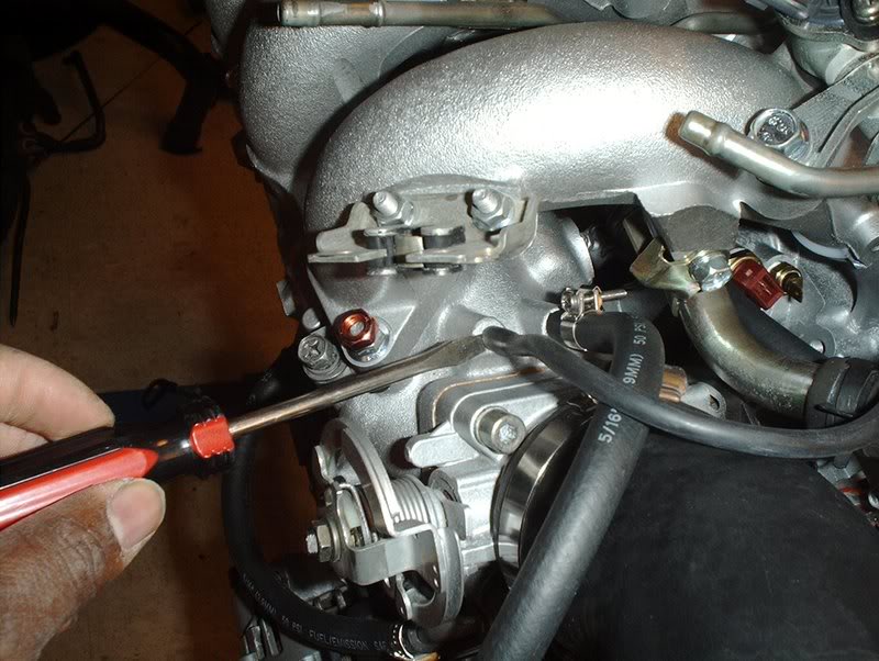
to here.
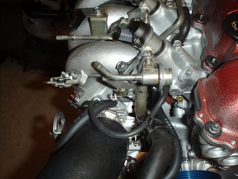
Like so and done. Probably have to make some changes later with the boost controller and whatnot.
Tools needed:
Hose
Hose clamps
Flathead screwdriver
Knife
For sometime I couldn't figure or find out where the hoses for the coolant line, water line, IACV and throttlebody go but now I know thanks to some help from the forum.
It was mainly these two off the coolant and water lines...
and this port off the water line.
I started with the port coming off the water line.
Cut the hose and it connects to the small port on the back of the IACV that points straight down....
like so. Somebody who's done this tell me if this is okay. I didn't want to cut the hose too short to keep it kink free.
The port coming off the coolant line goes to the other small port on the back of the IACV that points off to the side.
In order to keep this kink free as well I let it loop around slightly like so...
until it connects.
Next there was this one on the water line towards the sensor housing.
It connects to the port on the bottom left of the throttlebody, you know the one that points downward.
Then there is this one on the bottom right of the throttlebody.
It connects here to the port on the sensor housing...
like so.
And so.
Finally there's the smaller hose that goes from the port on the bottom of the fuel regulator here...
to here.
Like so and done. Probably have to make some changes later with the boost controller and whatnot.
Thread Starter
Contributing Member
Joined: Sep 2002
Posts: 1,192
From: Starkville, MS.
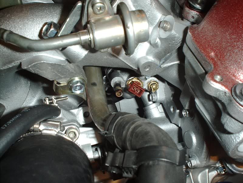
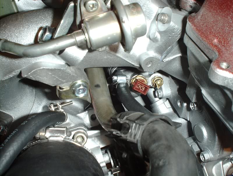
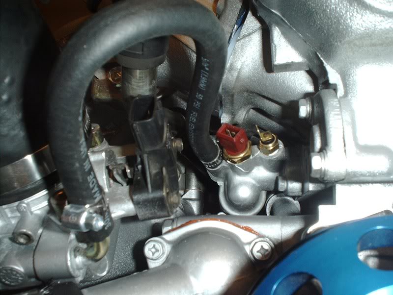
Fuel Injector Seal Replacement Continued....
During the replacement of my fuel injector seals I accidently dropped an injector and cracked the little yellow cap on the tip of the injector. So for fun I took an injector off my KA to see if it would fit the SR injector.
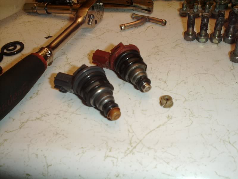
Sure enough, it did fit...problem solved!
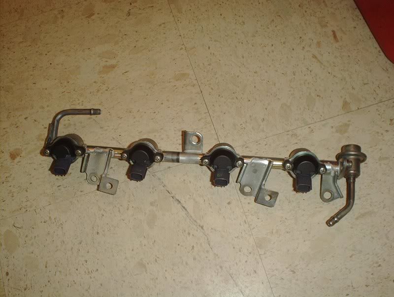
I put the injector in the rail with the rest.
Now I was ready to put the fuel rail back on the intake manifold. To do that there are four bolts, washers and insulators for mounting.
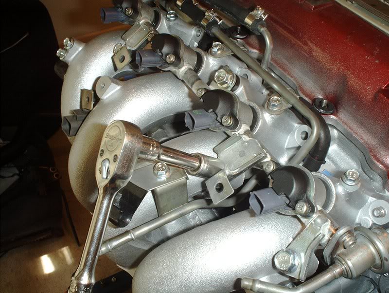
The rubber insolators go on first in between the intake manifold and the fuel rail, then the washer goes on the rail and the bolt goes in after that. The rail bolts get torqued to 15-20ft.lbs.
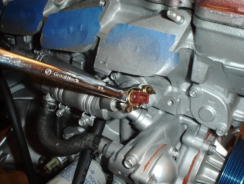
Next, the small hose on the top of the intake manifold needs to be connected to the fuel rail.
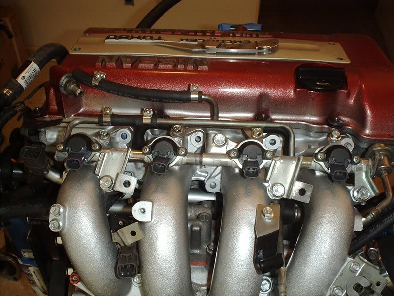
Finished.
Sure enough, it did fit...problem solved!
I put the injector in the rail with the rest.
Now I was ready to put the fuel rail back on the intake manifold. To do that there are four bolts, washers and insulators for mounting.
The rubber insolators go on first in between the intake manifold and the fuel rail, then the washer goes on the rail and the bolt goes in after that. The rail bolts get torqued to 15-20ft.lbs.
Next, the small hose on the top of the intake manifold needs to be connected to the fuel rail.
Finished.
Thread Starter
Contributing Member
Joined: Sep 2002
Posts: 1,192
From: Starkville, MS.
Hose Install Continued....
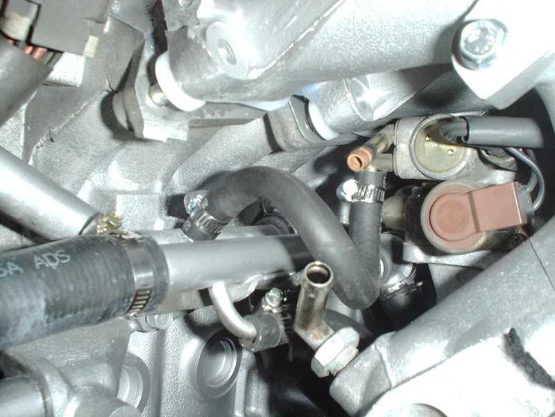
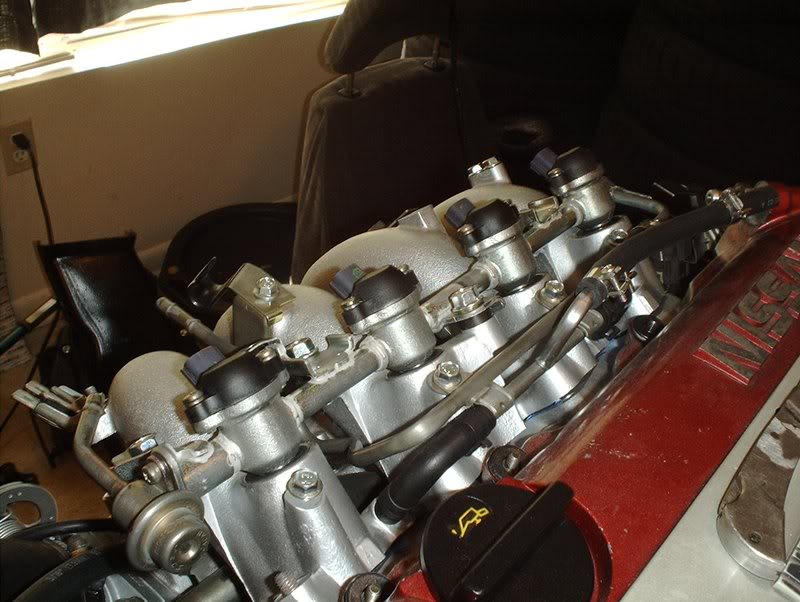
Turns out I had the hoses on the IACV routed backward and they were far too long...
so I trimmed the hoses and rerouted them back onto the IACV like so.
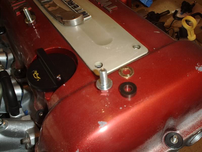
I also replaced my chipped up CAS cover while I was at it.
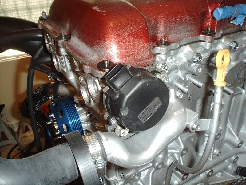
Old cover.
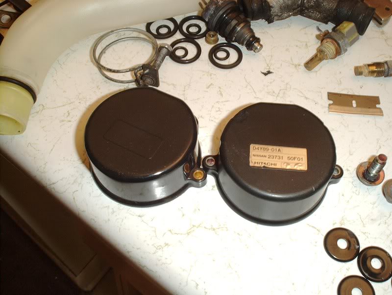
Old vs. new.
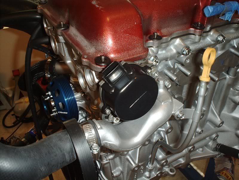
New cover.
so I trimmed the hoses and rerouted them back onto the IACV like so.
I also replaced my chipped up CAS cover while I was at it.
Old cover.
Old vs. new.
New cover.


