
DIY INTAKE MANIFOLD porting for Natural aspiration

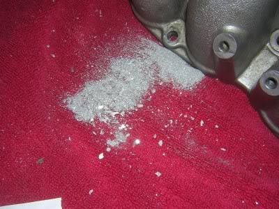
Finished grinding all of the lower runners today and began sanding down for polish. I am still waiting for a small shipment of the sanding flap wheels to come in. I have spent 4,1/2 hours on this project so far, and still no where near the completion I want it to be for proper design.
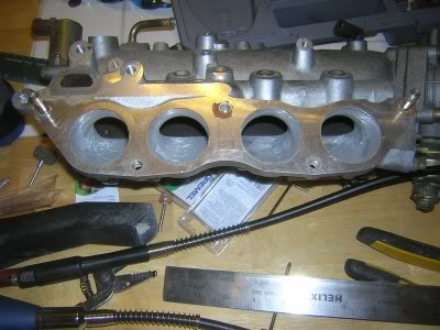
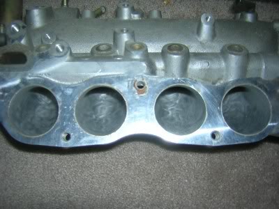
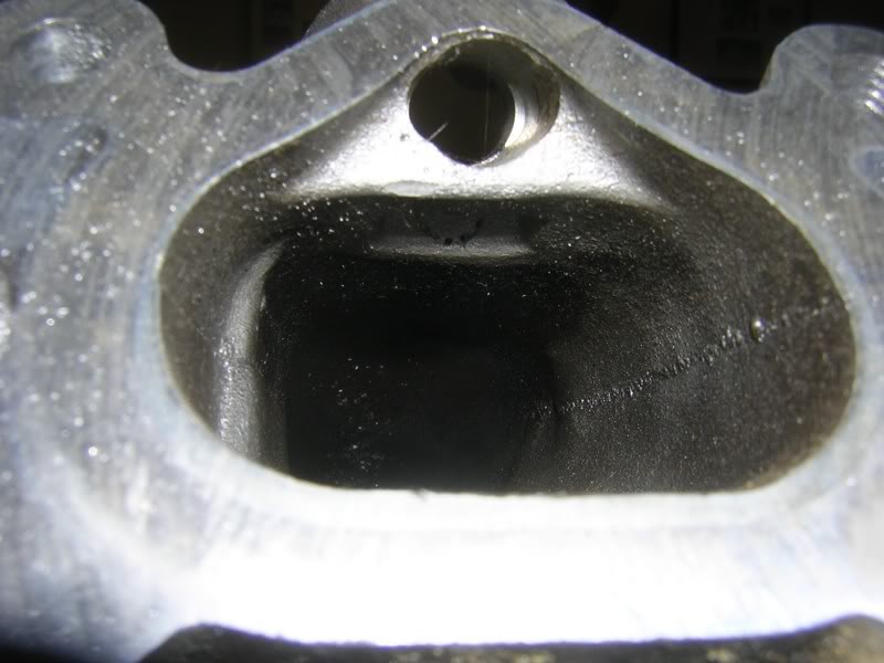
BEFORE
AFTER As you can see I've been getting messy, not good I will be cleaning this mess up.
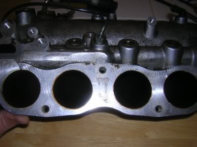
Now until the sanders come in I have been starting to collect data on the upper runners. What is interesting is that the upper manifold runners are almost 2,1/4MM larger in diameter than the lower half plenum runners. Not to mention the casting is dog poo.
What this means from what I have gathered is that the lower plenum runners are made smaller for smog emissions. What this does is that it creates a temporary choke hold on inlet air as the EGR opens and allows the exhaust gas to bypass atmospheric air. The diameter size of the lower stock runners definitely shows signs that the manifold is anemic when in high RPM use, especially for 2.4litre displacement. BTW this will also affect the intake manifold pressure on forced inducted KA's.
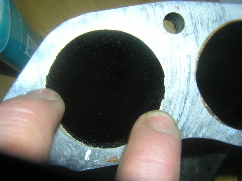
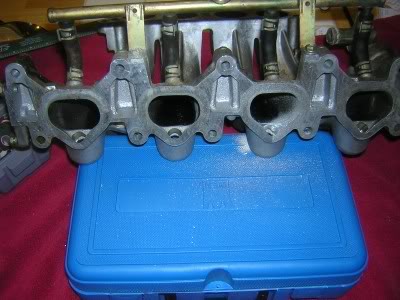
STOCK BOTTOM RUNNER DIAMETER
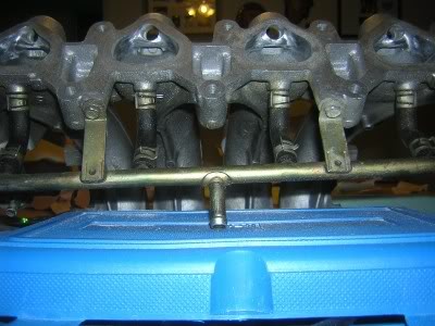
STOCK UPPER RUNNER DIAMETER
Now what I have started to pay close attention to is the casting of the upper runners. There isn't too much room for porting without decreasing the velocity.
The manifold does need to be cleaned up though around the casting welds.
More than likely I will just clean up the manifold on Saturday with a slight grind, sand and polish.
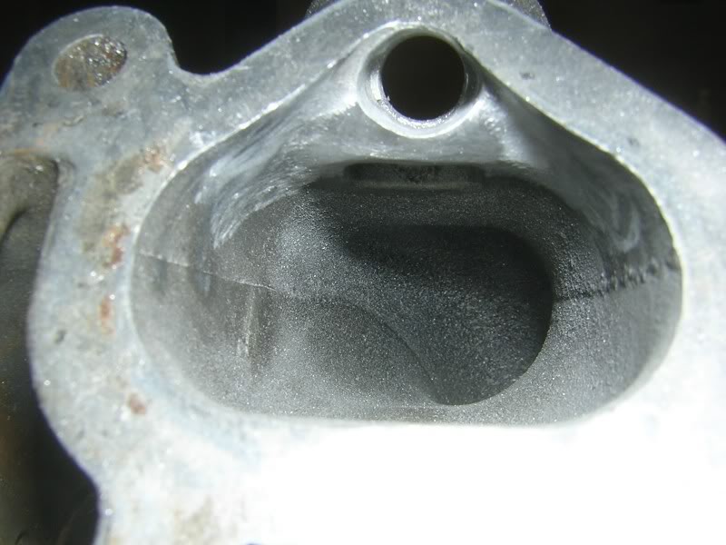
BEFORE
AFTER As you can see I've been getting messy, not good I will be cleaning this mess up.
Now until the sanders come in I have been starting to collect data on the upper runners. What is interesting is that the upper manifold runners are almost 2,1/4MM larger in diameter than the lower half plenum runners. Not to mention the casting is dog poo.
What this means from what I have gathered is that the lower plenum runners are made smaller for smog emissions. What this does is that it creates a temporary choke hold on inlet air as the EGR opens and allows the exhaust gas to bypass atmospheric air. The diameter size of the lower stock runners definitely shows signs that the manifold is anemic when in high RPM use, especially for 2.4litre displacement. BTW this will also affect the intake manifold pressure on forced inducted KA's.
STOCK BOTTOM RUNNER DIAMETER
STOCK UPPER RUNNER DIAMETER
Now what I have started to pay close attention to is the casting of the upper runners. There isn't too much room for porting without decreasing the velocity.
The manifold does need to be cleaned up though around the casting welds.
More than likely I will just clean up the manifold on Saturday with a slight grind, sand and polish.
Last edited by BigVinnie; May 15, 2007 at 11:16 PM.
Finished up the polish on the lower runners. So far I have spent 6,1/2 hours.
I went through using 80grit and 120grit wheel flap sanders. Then I used the 120 grit, and 320grit polishing wheels It seems that manufacturers don't carry many 400grit applications anymore for that fine finishing touch. Overall the work looks great and each runner is now at 45mm, rather than the stock 44mm. As you can see manifold porting and honing is a dieing art as it takes many hours to perfect what you want. The runners feel baby butt smooth inside. I could of polished more for an ultimate shine but then I wouldn't really be making anymore HP.
I've been asked; "Why do you care to polish the inside of the manifold isn't it suppose to be rough?"
Theres a big misconception here, there are 2 different types of manifold designs old school design (using carburation) uses what is known as a wet manifold design. For wet manifolds they are suppose to be rough in order to atomize the Air to fuel more efficiently and effectively. Dry manifolds inject fuel at the opening of the head or in the case of direct injection is injected directly into the chamber. Dry manifolds are much more effective in making power when they are smoothed out or polished.
I still have many hours to go before completion.
Last edited by BigVinnie; May 17, 2007 at 08:40 PM.

just to add to the wet and dry manifolds.
i had (died 2 years ago) a friend with a trans am (i think) his intake mani wasn't just rough, it was sharp. he told me the reason behind this but all i can remember was thinking about the tornado thing you put on your intake.
from what he told me and from what i've read, the rough mani is better suited for a carbed engine.
also i read somewhere that on fuel injected engines a smooth intake will increase top end hp but you'll lose torque at lower rpm's. while a rough intake will produce more torque and decent top end hp but with less acceleration. is this more or less correct?
LS engines use plastic manifolds that are extremely smooth in the inside of the runners and LS engines gain torque.
Last edited by BigVinnie; May 18, 2007 at 10:31 AM.
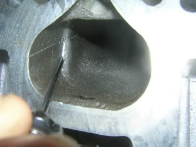
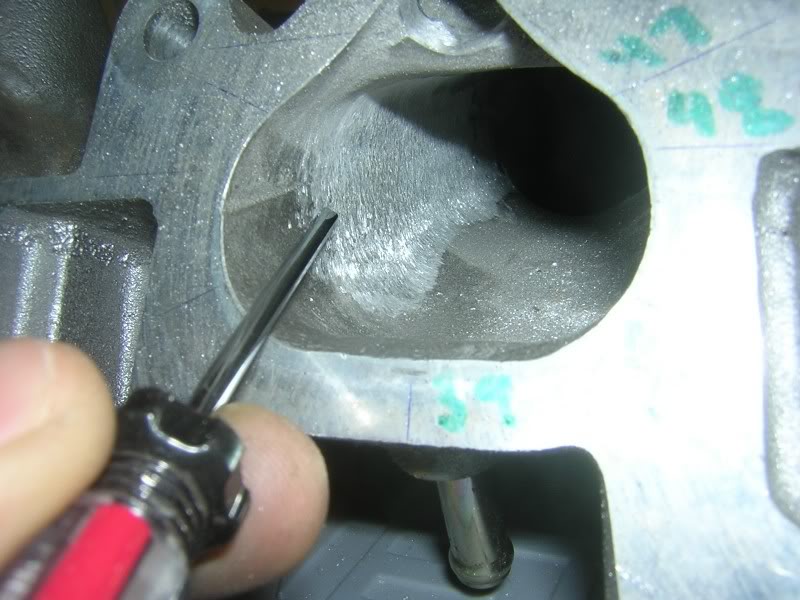
O.K I have a bit of a delay on my felpro gaskets it appears that someone in shipping screwed up so it won't be in until Monday or Tuesday of next week. No worries though I decided to move onto the injector bosses. They needed a lot of cleaning up.
Now I know some people like to remove the BOSSES, I definitely won't be doing that for natural aspiration. The Bosses have included in them a velocity tunnel that that allows for atomization to occur, the velocity charge through the boss allows for the Air and fuel to mix upon delivery. The only time I would think on removing the boss is if I went forced inducted, but that isn't the case here. So first I had to pick my point's. I used a tiny screw driver to show you the selected point of removal.
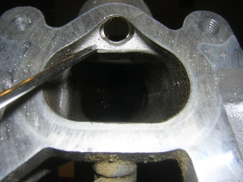
Now as you can see this part is extremely delicate when extruding the aluminum. In fact it is so delicate I have decreased the speed on the dremel to 10,000~13,000RPM, and I am taking my time.
In the processes I have increased the diameter of the injector boss, as well as smoothing out the contour around the injector boss, this will help to increase the velocity through the runner.
BEFORE

AFTER
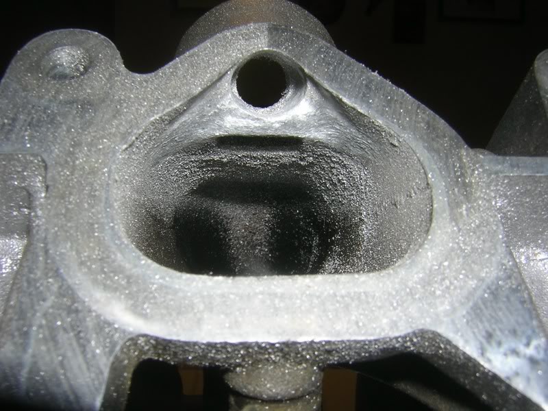
I found that the best grinder to use for this process is the bullet shaped grinder, it is best to stay away from the cylinder grinder unless I am working deep enough into the runners. Still this looks rough , but once the sand and polish is applied it will look better. Completion of one injector boss takes roughly an hour.
The best way to work on the bosses is to turn the manifold upside down.
Now I know some people like to remove the BOSSES, I definitely won't be doing that for natural aspiration. The Bosses have included in them a velocity tunnel that that allows for atomization to occur, the velocity charge through the boss allows for the Air and fuel to mix upon delivery. The only time I would think on removing the boss is if I went forced inducted, but that isn't the case here. So first I had to pick my point's. I used a tiny screw driver to show you the selected point of removal.
Now as you can see this part is extremely delicate when extruding the aluminum. In fact it is so delicate I have decreased the speed on the dremel to 10,000~13,000RPM, and I am taking my time.
In the processes I have increased the diameter of the injector boss, as well as smoothing out the contour around the injector boss, this will help to increase the velocity through the runner.
BEFORE
AFTER
I found that the best grinder to use for this process is the bullet shaped grinder, it is best to stay away from the cylinder grinder unless I am working deep enough into the runners. Still this looks rough , but once the sand and polish is applied it will look better. Completion of one injector boss takes roughly an hour.
The best way to work on the bosses is to turn the manifold upside down.
Last edited by BigVinnie; May 19, 2007 at 12:48 PM.

Thank you, I am doing my best to show you guy's a good presentation. I hope everyone can learn something from this. I promise, I won't fail. If anyone has any questions or suggestions let me know. I will be locking it once the project is complete to keep the threads integrity.

I have also been considering buying a house (Part of the Down payment) with the money and just waiting again for a rebuild, especially since housing prices are crashing down for home buyers right now. Every time my girlfriend (soon to be wife) looks at what I purchase for my cars she starts freaking out, and tells me "this is exactly why we'll never own a home it's always about you and your damn cars!!!" Yep that sums it up in a nut shell.
Last edited by BigVinnie; May 20, 2007 at 11:46 AM.
Today I almost completed everything with the bosses. I have not polished yet and that won't be done until every imperfection in the runners are corrected.
I used the bullet grinder and the 80grit wheel flap. After 3,1/2 hours my hands are shaking. As a reminder when you do the bosses even the flap wheel needs to run at 10,000 to 13,000 RPM as well, the sander can do as much damage to the aluminum as the grinder can. You must have both hands on the grinder at all times or it can run off the grinding path and do damage to the port, or the bosses. Please be carefull if you chose to do work around the bosses.
Here is the completion of the bosses. You probably noticed that I haven't taken the vacuum lines off yet. That really doesn't matter to me and everything will be getting stripped down for cleaning eventually.
BEFORE
MIDDLE STAGE

AFTER 80grit
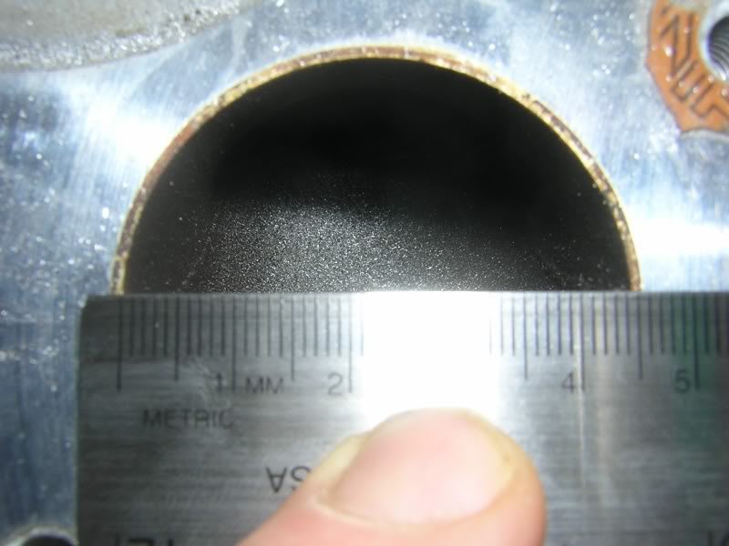
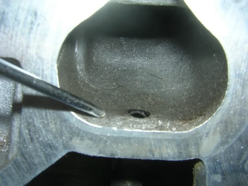
Gaskets still aren't in so now I am going to be moving into the runner to correct some SERIOUScasting imperfections. One casting imperfection sticks out like a sore thumb at almost 1.5mm as shown in this pic.
Something in the casting process didn't line up right, or the aluminum shrank to quick, it could also be one of NISSANS purposely engineered designs. In any case it has to go. This imperfection was noticed in runner 1, and runner 3, it definitely shows that some cylinders weren't making as much power as others as this cuts down on flow. These 2 cylinders could of experienced a 1 to 2 HP loss with an imperfection like this. This is one of the reasons why not even 2 of the same engineered engines will ever make the same HP on the dyno..
The second set of imperfections I wil be correcting is the lumps in each runner found right by the vacuum line.
More to come in the week...
I used the bullet grinder and the 80grit wheel flap. After 3,1/2 hours my hands are shaking. As a reminder when you do the bosses even the flap wheel needs to run at 10,000 to 13,000 RPM as well, the sander can do as much damage to the aluminum as the grinder can. You must have both hands on the grinder at all times or it can run off the grinding path and do damage to the port, or the bosses. Please be carefull if you chose to do work around the bosses.
Here is the completion of the bosses. You probably noticed that I haven't taken the vacuum lines off yet. That really doesn't matter to me and everything will be getting stripped down for cleaning eventually.
BEFORE
MIDDLE STAGE
AFTER 80grit
Gaskets still aren't in so now I am going to be moving into the runner to correct some SERIOUScasting imperfections. One casting imperfection sticks out like a sore thumb at almost 1.5mm as shown in this pic.
Something in the casting process didn't line up right, or the aluminum shrank to quick, it could also be one of NISSANS purposely engineered designs. In any case it has to go. This imperfection was noticed in runner 1, and runner 3, it definitely shows that some cylinders weren't making as much power as others as this cuts down on flow. These 2 cylinders could of experienced a 1 to 2 HP loss with an imperfection like this. This is one of the reasons why not even 2 of the same engineered engines will ever make the same HP on the dyno..
The second set of imperfections I wil be correcting is the lumps in each runner found right by the vacuum line.
More to come in the week...

Registered User
Joined: Mar 2007
Posts: 100
From: Fairmont, West Virginia
Hey vinnie i'm not trying to butt in but i was curious if you were going to be doing any head porting? and i was wondering how much material you will be removing if you are. Hopefully your just port matching. its the easiest and i think the most effective for the time spent. Also would it be a good idea to weld up those vacuum ports on the intake runners if you are getting rid of those vacuum lines. and just for clarification i speaking of the 4 vacuum ports directly underneath the fuel injectors. Thanks for your guidance vinnie Your always one of the guys i follow on this forum. Mostly cause you know your stuff especially about n/a. and you have the experience to back up anything you say. So all i can say is thank you for passing on your knowledge to everyone else.
Hey vinnie i'm not trying to butt in but i was curious if you were going to be doing any head porting? and i was wondering how much material you will be removing if you are. Hopefully your just port matching. its the easiest and i think the most effective for the time spent. Also would it be a good idea to weld up those vacuum ports on the intake runners if you are getting rid of those vacuum lines. and just for clarification i speaking of the 4 vacuum ports directly underneath the fuel injectors. Thanks for your guidance vinnie Your always one of the guys i follow on this forum. Mostly cause you know your stuff especially about n/a. and you have the experience to back up anything you say. So all i can say is thank you for passing on your knowledge to everyone else.
I won't be port matching until a rebuild. I am also just going to replace the vacuum lines with new ones. As far as doing the manifold work I am doing it because it is one of those modifications that I need to get out of the way even if I rebuild in the near future or not. Regardless this is a mod that will show gains since I already have an older manifold with SCV's.
When a shop does get to rebuild for me I will be doing the stuff that I like to do such as the port and polish of the head. Besides port and polishing is getting ridiculous in price, mostly because of the amount of hours it takes.
Eventually I will be doing the head porting and make a thread on it. Head porting takes a lot more time and hours than the manifold porting does and it needs to be tested on a flow bench for accuracy (which cost me money).
Last edited by BigVinnie; May 21, 2007 at 10:13 AM.
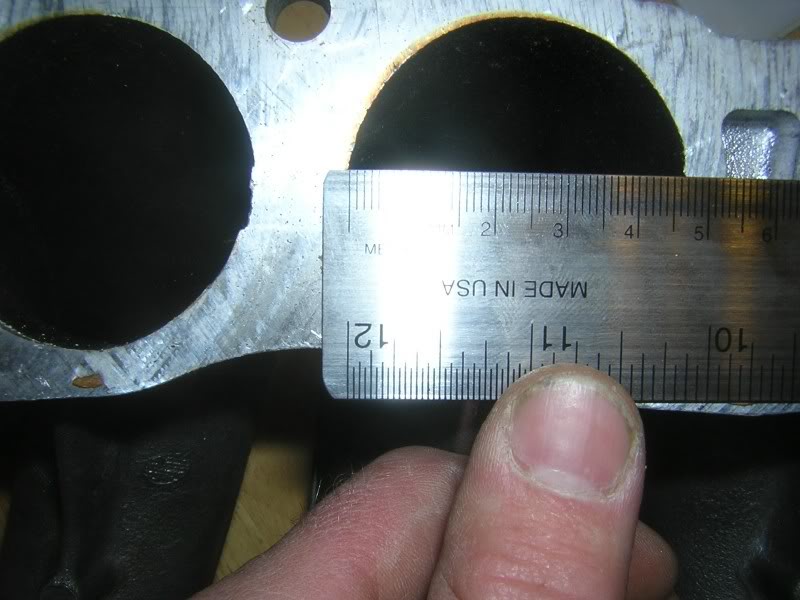
Today I plotted out the manifold ports to the upper runners. Because the ports are not perfectly round I needed to plot some points to establish how well these ports will flow when compared to the porting I did to the lower runners.
As you can see it's all averaging. Select 4 points that are the furthest points from each other. Add that total and divide by 4. This determines what points you select to grind and make even. It will work to keep accurate flow numbers.
This is the numbers that I came up with.
39MM+47MM+48MM+47.5MM/4=45.3MM Diameter/Flow
39MM+47.5MM+48MM+48MM/4=45.6 MM Diameter/Flow
39MM+47MM+48MM+48MM/4=45.5MM Diameter/Flow
39MM+47MM+47MM+48MM/4=45.25MM Diameter/Flow
I'll try to make them all at 45.6MM. That way they are equal, and the added fluid mass of fuel can mix air. As you can see not much work will be done. The area's that will be selected can be found in the plotted points.
Last edited by BigVinnie; Aug 20, 2007 at 08:02 PM. Reason: Math was wrong
 .
.
Started on one of the imperfections today and I am still not done extruding the aluminum from it. I was only able to put 1 hour of progress in today. The imperfection runs almost a total of 80MM into the runner so I am extruding quite a bit of the aluminum from the wall of the runner.
BEFORE


AFTER
EXTRUDED ALUMINUM WASTE
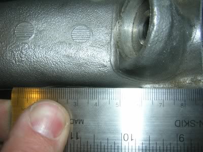
Here is a pic of how bad the imperfection is. You can actually see it from the exterior of the manifold. This is in fact a really bad casting imperfection ranging from 1.5~2MM in depth. I used a ruler as my straight edge so you can see the imperfection pay no attention to the ruler markings in this pic.
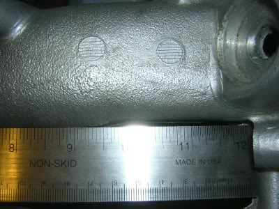
The imperfection runs almost 80MM into the runner.
BEFORE
AFTER
EXTRUDED ALUMINUM WASTE
Here is a pic of how bad the imperfection is. You can actually see it from the exterior of the manifold. This is in fact a really bad casting imperfection ranging from 1.5~2MM in depth. I used a ruler as my straight edge so you can see the imperfection pay no attention to the ruler markings in this pic.
The imperfection runs almost 80MM into the runner.
Last edited by BigVinnie; May 27, 2007 at 12:49 PM.