
My S13 SR20DET Prep

Thread Starter
Contributing Member
Joined: Sep 2002
Posts: 1,192
From: Starkville, MS.

Registered User
Joined: Apr 2007
Posts: 316
From: Ft. Riley Kansas
Are you planning on rebuilding the head with OEM parts or just running whats in there.
I know you have to be anxious to ****ing get this motor in.
++ I'm happy you came back to post. I love this thread.
fooooo sho!
I know you have to be anxious to ****ing get this motor in.
++ I'm happy you came back to post. I love this thread.
fooooo sho!
Thread Starter
Contributing Member
Joined: Sep 2002
Posts: 1,192
From: Starkville, MS.
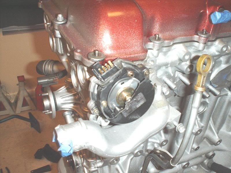
Crank Angle Sensor Replacement
I swapped out my busted crank angle sensor.
Tools needed:
Screwdriver
Socket wrench
12mm socket
27mm socket
Oil
This sensor was fine when I got the motor...don't ask me how it got busted because I don't want to talk about it.
I got another CAS from a forum member and at a great price too.
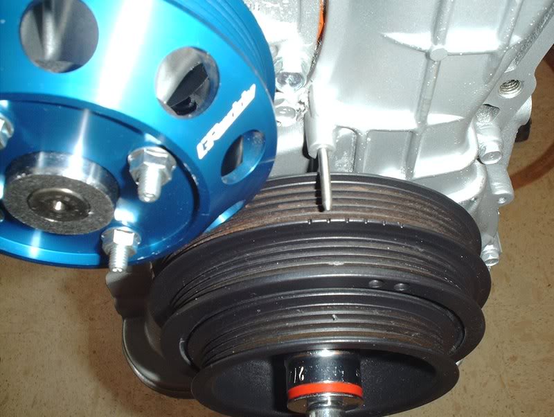
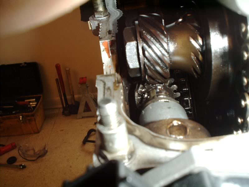
If you look on your crank pulley you will see a group of little notches on one side of it, these are the timing marks. Use the 27mm socket and wrench to move your crank pulley to the notch that is second from the left, this is TDC or top dead center.
You'll need a 10mm socket to remove the valve cover bolts and the valve cover so you can see where the timing marks are on the crank angle sensor.
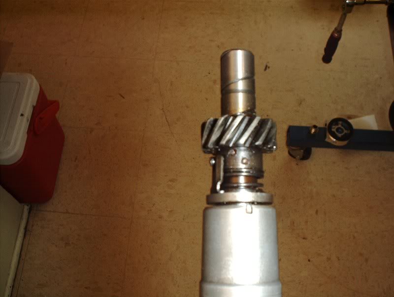
If you look closely on the CAS you will see a notch on the bottom and above that notch on the shaft you will see two circles, one on the top and one on the bottom. These are the marks that you will use to set the timing to TDC later.
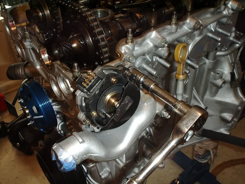
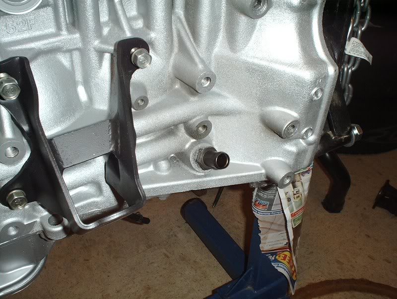
Use a 12mm socket or a screwdriver to remove the two bolts holding the CAS in the block.
Take a moment to look at where the timing marks on the CAS are at TDC. The second circle or timing mark on the shaft of the CAS is aligned perfectly with the notch on the lower part of the CAS. This is how I want the new CAS positioned.
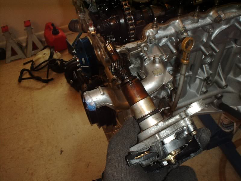
Grab the CAS and tug on it until you pop it out.
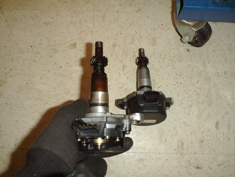
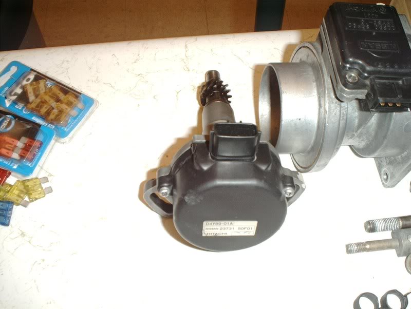
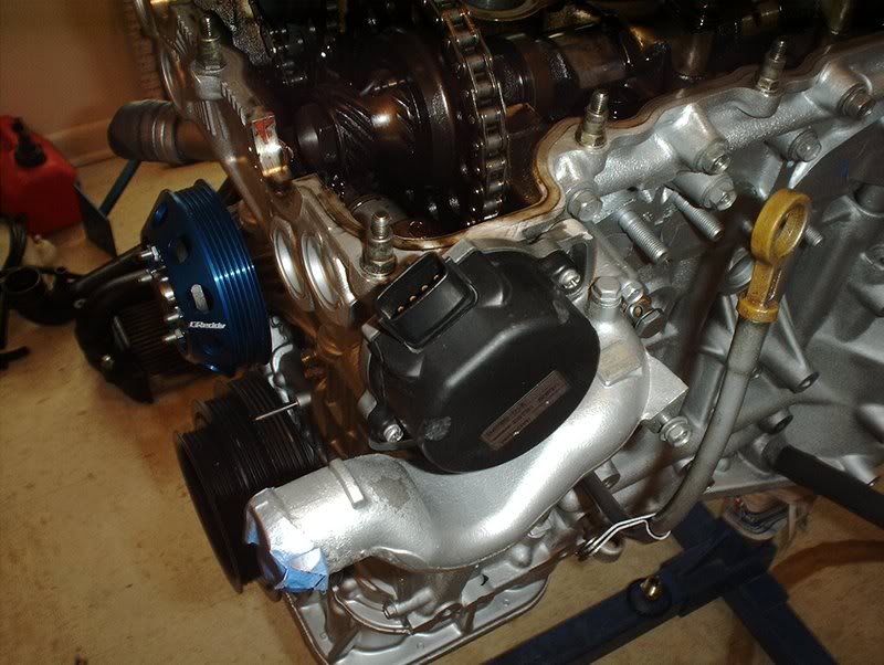
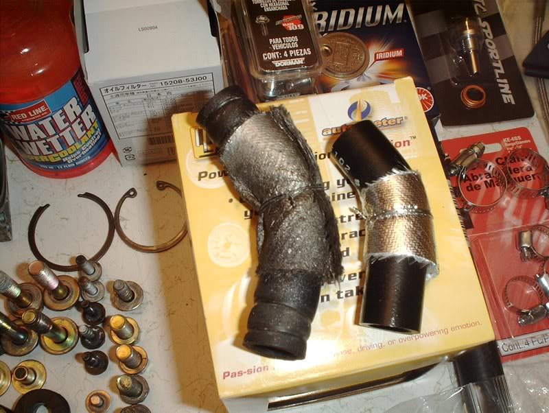
The new and the old. Dip the replacement CAS in some oil before you insert it back into the block.
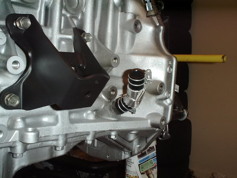
Now for insertion. This is what has to happen, you line up the first circle on the shaft of the CAS with the notch below it and when you insert back into the block the gears will turn slightly causing the second circle or timing mark to become aligned with the notch putting you at TDC.
I lined the first timing mark up, inserted it and it lined up perfectly with the second timing mark.
Hopefully I won't have to adjust timing when I start the engine up (that is if it's a good engine...man I hate to think that I could be doing all this for nothing) and it'll fire up the first time.
Tools needed:
Screwdriver
Socket wrench
12mm socket
27mm socket
Oil
This sensor was fine when I got the motor...don't ask me how it got busted because I don't want to talk about it.
I got another CAS from a forum member and at a great price too.
If you look on your crank pulley you will see a group of little notches on one side of it, these are the timing marks. Use the 27mm socket and wrench to move your crank pulley to the notch that is second from the left, this is TDC or top dead center.
You'll need a 10mm socket to remove the valve cover bolts and the valve cover so you can see where the timing marks are on the crank angle sensor.
If you look closely on the CAS you will see a notch on the bottom and above that notch on the shaft you will see two circles, one on the top and one on the bottom. These are the marks that you will use to set the timing to TDC later.
Use a 12mm socket or a screwdriver to remove the two bolts holding the CAS in the block.
Take a moment to look at where the timing marks on the CAS are at TDC. The second circle or timing mark on the shaft of the CAS is aligned perfectly with the notch on the lower part of the CAS. This is how I want the new CAS positioned.
Grab the CAS and tug on it until you pop it out.
The new and the old. Dip the replacement CAS in some oil before you insert it back into the block.
Now for insertion. This is what has to happen, you line up the first circle on the shaft of the CAS with the notch below it and when you insert back into the block the gears will turn slightly causing the second circle or timing mark to become aligned with the notch putting you at TDC.
I lined the first timing mark up, inserted it and it lined up perfectly with the second timing mark.
Hopefully I won't have to adjust timing when I start the engine up (that is if it's a good engine...man I hate to think that I could be doing all this for nothing) and it'll fire up the first time.
Contributing Member
Joined: Feb 2005
Posts: 2,586
From: 神奈川県,日本
yea its always stressfull spending all that time and thinking about if it doesnt fire...ur doing a good job though so im sure u wont have any problems, if so itll be something minor like forgetting to plug something in lol
Thread Starter
Contributing Member
Joined: Sep 2002
Posts: 1,192
From: Starkville, MS.
Vaccuum/Coolant/Water Hoses
As far as the hoses go I know that I have way too much hose on there and that I have pretty much no idea where most go. I have been looking at pics of engines online and looking through my magazines and FSM to figure it out but while we are on the subject I have more hose questions.
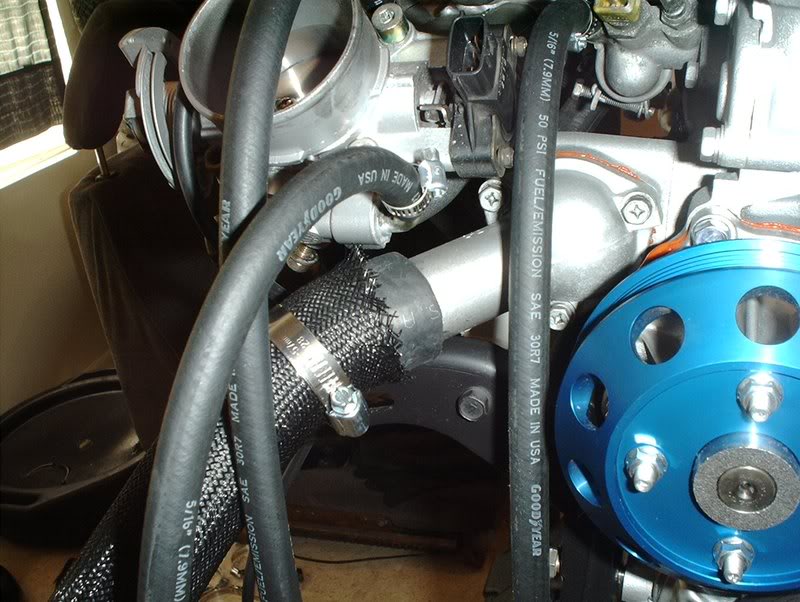
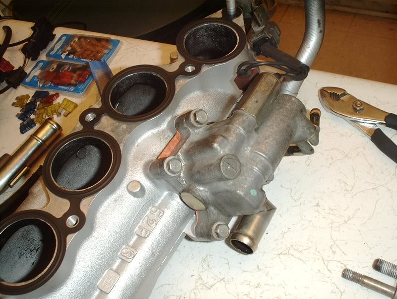
A forum member pointed out to me that the hose on the sensor housing goes to the hose near the TPS.
I know that the IACV hose goes here on the big outlet on the IACV and connects to the small port on the coldpipe....
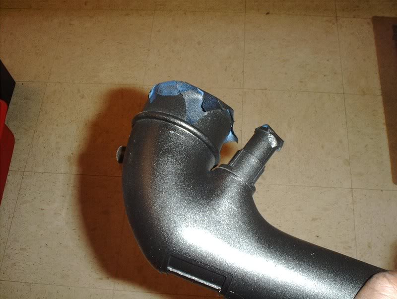
here!
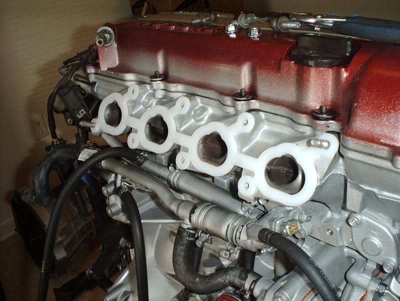
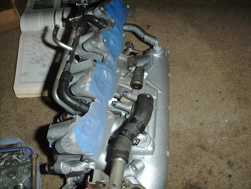
I need to know where these two hoses on the water and coolant lines go to?
I also need to know where the hoses for the two small outlets on the side of the IACV go?
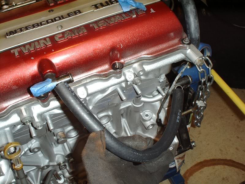
The hose from this outlet goes to one side of the T on the valve cover.
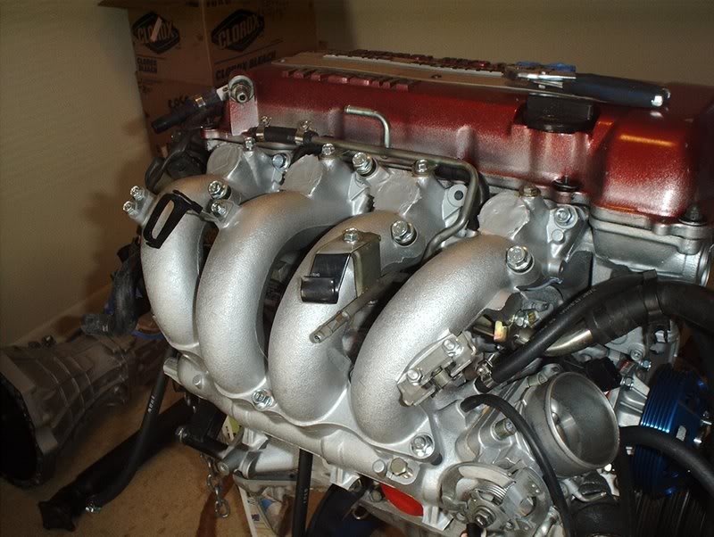
The bigger hose on the top of the throttle body goes accross the front of the engine over to the intake correct? Where does the small hose on the throttlebody go. I was researching and I think it has something to do with boost.
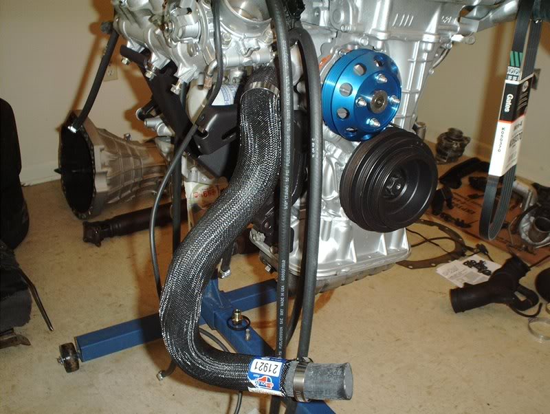
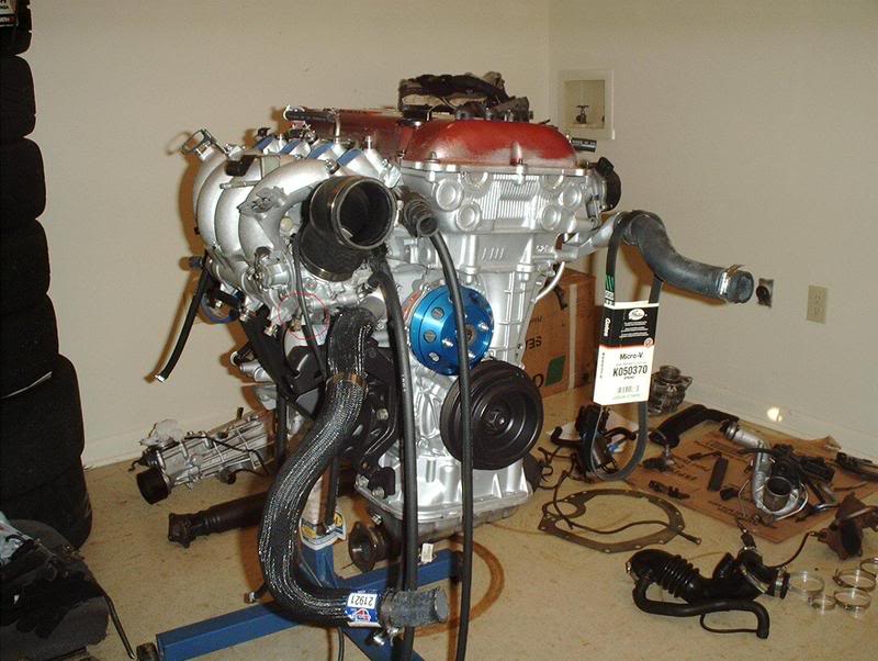
There is a small outlet on the lower left of the throttlebody that bends down...where does the hose on this outlet go or come from?
A forum member pointed out to me that the hose on the sensor housing goes to the hose near the TPS.
I know that the IACV hose goes here on the big outlet on the IACV and connects to the small port on the coldpipe....
here!
I need to know where these two hoses on the water and coolant lines go to?
I also need to know where the hoses for the two small outlets on the side of the IACV go?
The hose from this outlet goes to one side of the T on the valve cover.
The bigger hose on the top of the throttle body goes accross the front of the engine over to the intake correct? Where does the small hose on the throttlebody go. I was researching and I think it has something to do with boost.
There is a small outlet on the lower left of the throttlebody that bends down...where does the hose on this outlet go or come from?
Registered User
Joined: Dec 2006
Posts: 434
From: VA
i can't answer the iacv one.
but from the throttle body. I have mine running like so:
top right tb outlet goes to fuel pressure regulator
top left runs over to the turbo side to a T. one line from the T goes to the waste gate, the other goes to the bov. i have the one going to the bov t'd again for a boost gauge
i run a hose from the valve cover t to my intake to. the other side of the is connect to some canister (charcoal/oil catch?)
the port on the bottom of the tb, isn't vacuum. so just block it. you may be talking about the coolant ports on the tb. you can bypass the coolant from the tb if you want. i would. www.bumnah.com/fsms they should have one for the sr with the coolant flow diagram.
iacv runs to the intake tube near the tb.
vacuum lines from the booster runs towards the back of the intake manifold.
i have no emissions equipment.
Last edited by Bumnah; Feb 29, 2008 at 04:36 PM.

Thread Starter
Contributing Member
Joined: Sep 2002
Posts: 1,192
From: Starkville, MS.
i can't answer the iacv one.
but from the throttle body. I have mine running like so:
top right tb outlet goes to fuel pressure regulator
top left runs over to the turbo side to a T. one line from the T goes to the waste gate, the other goes to the bov. i have the one going to the bov t'd again for a boost gauge
i run a hose from the valve cover t to my intake to. the other side of the is connect to some canister (charcoal/oil catch?)
the port on the bottom of the tb, isn't vacuum. so just block it. you may be talking about the coolant ports on the tb. you can bypass the coolant from the tb if you want. i would. www.bumnah.com/fsms they should have one for the sr with the coolant flow diagram.
iacv runs to the intake tube near the tb.
vacuum lines from the booster runs towards the back of the intake manifold.
i have no emissions equipment.
but from the throttle body. I have mine running like so:
top right tb outlet goes to fuel pressure regulator
top left runs over to the turbo side to a T. one line from the T goes to the waste gate, the other goes to the bov. i have the one going to the bov t'd again for a boost gauge
i run a hose from the valve cover t to my intake to. the other side of the is connect to some canister (charcoal/oil catch?)
the port on the bottom of the tb, isn't vacuum. so just block it. you may be talking about the coolant ports on the tb. you can bypass the coolant from the tb if you want. i would. www.bumnah.com/fsms they should have one for the sr with the coolant flow diagram.
iacv runs to the intake tube near the tb.
vacuum lines from the booster runs towards the back of the intake manifold.
i have no emissions equipment.
Thread Starter
Contributing Member
Joined: Sep 2002
Posts: 1,192
From: Starkville, MS.
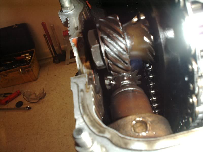
Turbo Oil Return Line/Oil Dipstick
Got some new parts in today.
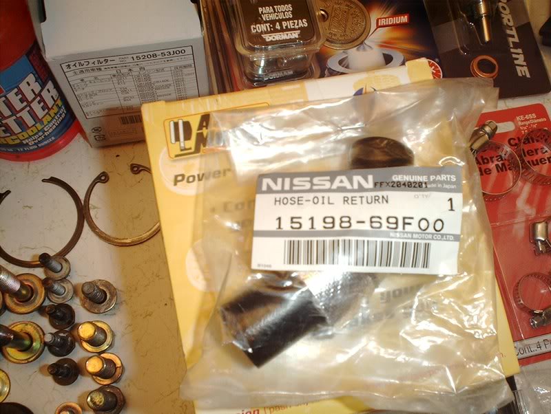
Turbo Oil Return Line Part#: 15198-69F00.
Strange, the old line is longer than the new line?????
Remove the old line....
replace with the new and don't forget about the hardware.
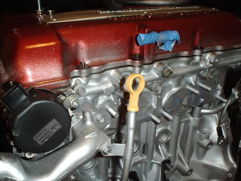
Oil Dipstick
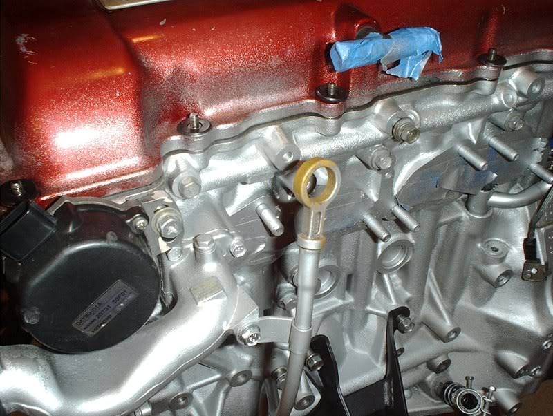
Not really a part that screams to be replaced.
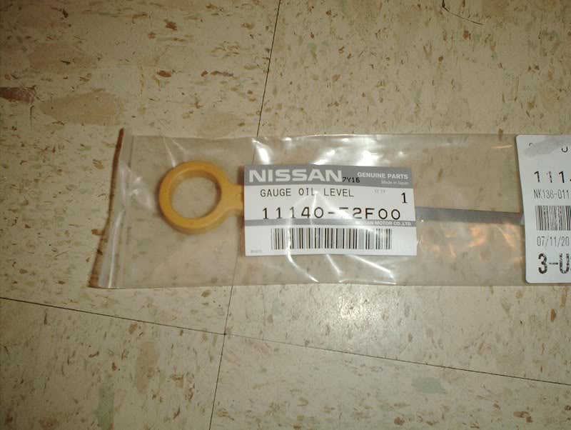
Oil Dipstick Part#: 11140-52F00.
Turbo Oil Return Line Part#: 15198-69F00.
Strange, the old line is longer than the new line?????
Remove the old line....
replace with the new and don't forget about the hardware.
Oil Dipstick
Not really a part that screams to be replaced.
Oil Dipstick Part#: 11140-52F00.